Every engineering team has the experience of watching a senior engineer produce a complex assembly in an afternoon while a junior engineer takes three days to produce something less complete. The difference is rarely intelligence or even technical CAD skill. It is almost always the compound advantage of reusable assets: templates that pre-populate the correct settings, library components that drop into place without being modeled from scratch, standard parts that carry all their properties, connections, and documentation already built in.
A well-built reusable CAD library is the infrastructure that makes engineering teams consistently faster, more consistent, and less error-prone than teams working without one. It is also one of the most consistently under-built assets in engineering organizations, not because teams do not understand its value, but because building it correctly requires deliberate architecture, governance discipline, and ongoing maintenance that feel like overhead in the middle of a delivery-focused project schedule.
The result of this underinvestment is a library built organically, one copied file and one downloaded model at a time, that grows into a collection of components with inconsistent quality, inconsistent naming, unknown reliability, and no governance. Engineers are never sure whether a library component is current, correct, or trustworthy. They start modeling from scratch, duplicating effort across the team, and the library’s potential value goes unrealized.
This article provides the architecture, the build process, the governance framework, and the platform-specific tool knowledge to build a CAD library that engineers actually use. It covers all six tiers of a complete library system, from drawing templates to supplier-provided geometry. It covers the validation workflow that keeps the library trustworthy. It covers the ROI calculation that justifies the investment to leadership. And it covers the lifecycle disciplines that keep the library healthy over years of active use.
Why Most CAD Libraries Fail Before They Deliver Value
The failure mode of a CAD library is almost always the same regardless of the organization, the CAD platform, or the industry. The library starts with good intentions and a burst of productive initial investment. A folder is created. Some templates are dropped in. A few downloaded models are added. An engineer contributes a part they just finished that might be useful to others. After six months, the folder has grown, but no one is entirely sure what is in it, how current any of it is, or whether the components were built to any standard.
The library becomes a secondary option rather than the default starting point. Engineers use it occasionally when they happen to know a relevant component exists, but they do not trust it enough to rely on it systematically. The productivity gains that motivated the initial investment are never realized.
The Trust Problem Is a Quality Problem
The root cause of library failure is almost always insufficient quality control at the point of entry. When any engineer can contribute any component to the library without review, the library inherits the quality level of the least careful contributor. When supplier-provided models are downloaded and placed in the library without validation, the library inherits whatever errors exist in those models. When templates are created once and never updated as standards evolve, the library drifts out of alignment with current practice.
Engineers are rational actors. When a library component has failed them once by producing a rebuild error, a wrong dimension, or an incorrect material property, they stop trusting the library. Once trust is lost, it is difficult to rebuild, because the history of past failures makes engineers skeptical of even the correctly built components that exist alongside the problematic ones.
The Library Contamination Problem
Library contamination is what happens when a poorly built component enters the library and is reused across multiple projects before the error is discovered. A fastener with an incorrect thread pitch. A bearing with the wrong bore tolerance. A standard bracket with a dimension that was correct for the project where it was originally designed but is wrong as a general standard. Each use of the contaminated component spreads the error further, and when the problem is eventually discovered, the correction must be applied across every project that used the component.
The contamination problem is geometrically more damaging than a single modeling error because it multiplies. An error that affects one part in one project costs one engineer some hours to fix. The same error in a library component used in twenty projects across two years costs twenty times as much to find and correct, plus the investigation time to identify every instance of use. This is why the quality gate at library entry is not bureaucratic overhead. It is a compounding investment in error prevention.
| The Fundamental Principle A CAD library is only as valuable as the trust that engineers place in it. Trust is earned by quality control at entry and maintained by governance over time. A library that is fast to build but low in quality will be used sparingly and will deliver a fraction of its potential value. A library that is slower to build but rigorously controlled will be used as the default starting point and will deliver compounding productivity returns across every project that uses it. |
The Six-Tier Library Architecture: A Framework That Scales
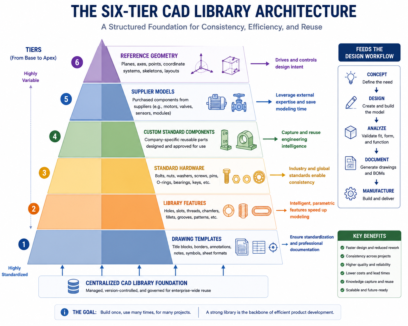
The most effective CAD libraries are not flat collections of files. They are structured in tiers that correspond to different types of reusable assets, each with its own creation process, its own governance rules, and its own use pattern. Understanding this tier structure is the prerequisite for building a library that remains organized, trustworthy, and useful as it grows.
| Library Tier | Content Type | Who Creates | Who Uses | PDM Control Level |
| Tier 1: Templates | Part, assembly, drawing templates with pre-set standards | CAD Manager / Lead Engineer | Every engineer on every new file | Locked, versioned, admin-only edit |
| Tier 2: Library Features | Reusable geometry patterns (UDF, iFeature, Library Feature) | Senior Engineers | Engineers adding standard features to parts | Controlled, approved before release |
| Tier 3: Standard Parts | Fasteners, bearings, seals, standard hardware | CAD Manager + Procurement | Engineers placing hardware in assemblies | Fully controlled, part number linked |
| Tier 4: Custom Standard Components | Company-designed reusable parts and sub-assemblies | Design team, reviewed by CAD Mgr | Engineers assembling product families | PDM-controlled, revision-managed |
| Tier 5: Supplier / Vendor Models | Purchased component 3D models from suppliers | Downloaded and validated, not designed | Engineers placing purchased parts | Validated before entry, read-only |
| Tier 6: Reference Geometry | Coordinate systems, fixture datums, jig geometry | Manufacturing / Tooling Engineers | Manufacturing, inspection, tooling teams | Project-specific, archived with project |
Why Tier Separation Matters in Practice
Mixing asset types in a flat library structure creates confusion about what each file is for and how it should be used. A drawing template and a fastener model look identical in a folder view, but they serve completely different purposes, require different creation processes, and carry different governance requirements. Separating them into explicit tiers makes the library navigable, makes governance rules clear, and makes the contribution process unambiguous for engineers who want to add new assets.
Tier separation also allows different governance strictness at each level. Tier 1 templates and Tier 3 standard hardware must be locked and admin-controlled because an error in these assets propagates to every new file and every assembly in the organization. Tier 4 custom standard components can have lighter governance because they are less universally applied. Tier 6 reference geometry can be project-specific and does not need to meet library quality standards because it serves a narrow, well-understood purpose within one project context.
Tier 1: Building the Template Layer That Everything Else Depends On
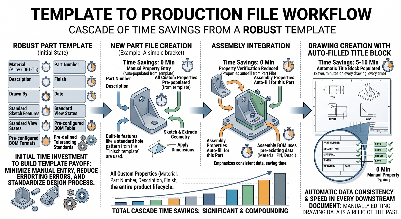
Templates are the foundational layer of the library and the highest-leverage asset in it. Every part file, every assembly, every drawing that any engineer creates in your organization starts from a template. A well-designed template pre-configures every standard setting that would otherwise require manual setup: the unit system, the document properties, the custom property fields, the material database connection, the drawing sheet format, the title block, and the default view scale. An engineer opening a correct template is seconds away from productive work. An engineer setting up a new file from scratch is ten to thirty minutes away.
What a Complete Part Template Contains
A production-ready part template is not just a blank part file saved as a template. It is a pre-configured engineering document that enforces your team’s standards automatically. Before the engineer draws a single line, the template has already done the following:
- Unit system: Millimeters and kilograms, or inches and pounds, set at the document level and impossible to accidentally change without explicitly overriding the template setting.
- Custom property fields: Part number, description, material, surface finish, revision, drawn-by, approved-by, and any other properties that feed the drawing title block or the BOM. Every field exists and is labeled correctly from the moment the file is created.
- Material database linked: The material library is connected so engineers can select materials from the approved list rather than typing free-form text that creates BOM inconsistencies.
- Reference geometry pre-built: The three standard reference planes are named according to your team convention (Top, Front, Right or XY, YZ, XZ depending on your standard) rather than the CAD tool’s default names that vary between platforms.
- Feature tree started: An origin folder, any company-standard reference geometry that belongs in every part, and any annotation notes that must appear in every model are already present.
- Default display settings: Edge display, face color convention, and any visual standards that the team applies uniformly are pre-set so every model looks consistent without engineer intervention.
What a Complete Drawing Template Contains
The drawing template is the most visible template in the library because it is what suppliers, manufacturing, quality, and customers see. Its configuration directly affects the professional presentation of every engineering document the team produces.
- Title block: Fully formatted with all mandatory fields, linked to the model’s custom properties so that part number, description, revision, and other fields auto-populate when the drawing is created.
- Sheet formats: Multiple sheet sizes (A4, A3, A2, A1, or B, C, D, E depending on your region) pre-formatted with your logo, border, and title block at the correct scale.
- Dimensioning standards: ASME Y14.5 or ISO 1101 annotation standards set at the document level so that all GD&T symbols, datum triangles, and feature control frames use the correct symbol set automatically.
- Layer or display state standards: Pre-configured layers for dimensions, notes, centerlines, and hidden lines with the correct line weights and styles for your organization’s drawing standard.
- Note blocks: Any standard notes that appear on every drawing, such as general tolerance callouts, surface finish standards, or material specification formats, are already placed and formatted.
| Setup Investment vs. Return A complete set of part, assembly, and drawing templates for a mechanical engineering team takes two to three days to build correctly. Once built and deployed through the PDM system, those templates save every engineer in the team 20 to 30 minutes on every new file they create. For a team of ten engineers creating five new files per week each, the template investment breaks even in approximately two weeks and continues delivering returns indefinitely. |
Tier 2: Library Features, UDFs, and iFeatures for Reusable Geometry Patterns
Between templates (which set up a file) and full part models (which are complete components) sits a middle tier of reusable assets that most engineers are unaware of: library features. A library feature is a reusable geometry pattern that can be inserted into any part at any location, sized according to the local geometry, and positioned as needed. It is not a complete part. It is a parametric geometry recipe that can be applied to many different parts.
The most obvious example is a fastener hole pattern. Every time an engineer creates a counterbored hole for an M8 socket cap screw, they perform the same sequence of operations: a circular sketch, an extrude-cut for the clearance diameter, another extrude-cut for the counterbore diameter, and a depth specification for each. A library feature encapsulates this entire sequence into a single drag-and-drop operation. The engineer drags the M8 clearance hole library feature onto a face, specifies the depth, and the full hole geometry is created in one step.
SolidWorks Library Features
SolidWorks Library Features are saved as .sldlfp files and stored in a location configured as the library feature folder in the SolidWorks options. They appear in the Design Library task pane and can be dragged directly onto faces in the active part. A library feature can include multiple features (the sketch plus the two cuts in the counterbore example), references (the face to apply the feature to), and configurable dimensions (the hole depth, the edge distance) that the engineer specifies during placement.
Effective SolidWorks Library Features are built with reference geometry that allows flexible placement: a reference point that can be positioned anywhere on the target face, dimensions that reference the feature’s own geometry rather than the parent part’s geometry so they remain valid regardless of where the feature is placed. Library features that are rigidly anchored to specific coordinates in their host part will not transfer correctly to different parts with different geometries.
PTC Creo User-Defined Features (UDFs)
Creo UDFs (User-Defined Features) function similarly to SolidWorks Library Features but with stronger parameterization capabilities. A UDF is saved as a standalone feature file and can be referenced by any Creo part file. When placed, the UDF prompts the engineer to specify the reference geometry (the face, edge, or datum to anchor the feature to) and any variable dimensions. Creo UDFs support dependency references, meaning the placed feature can reference existing geometry in the host part for size calculations, enabling more adaptive placement behavior than is typically achievable with SolidWorks Library Features.
Creo also supports Group UDFs, which combine multiple features into a single reusable group that can be propagated to all members of a Family Table simultaneously, making UDFs a natural companion to the configuration management workflows common in Creo-based engineering environments.
Autodesk Inventor iFeatures
Inventor iFeatures are the Inventor equivalent, stored as .ide files in the iFeatures folder configured in Inventor’s project settings. Like UDFs and Library Features, iFeatures capture parametric geometry patterns and allow flexible placement. Inventor’s iFeature creation process is particularly well-integrated with the Inventor design environment, allowing features to be extracted from existing parts by selecting them in the feature tree and using the Create iFeature command rather than building the feature from scratch in a separate file.
This extraction approach is valuable for teams migrating to a library-first workflow: instead of starting from scratch, engineers can extract the best-built examples of common feature patterns from recent designs and convert them directly into iFeatures for the library. This both populates the library quickly with high-quality examples and establishes the quality standard that future library contributions should meet.
Tier 3: Building the Standard Hardware Library Correctly
Standard hardware, fasteners, bearings, seals, springs, and connectors, is the component category that teams most commonly try to address through external download sources. Sites like 3D ContentCentral, TraceParts, and McMaster-Carr provide downloadable models for millions of standard parts. The temptation is to download whatever is needed at the moment and add it to the library. This approach is faster to start but creates the quality and consistency problems that make the library untrustworthy over time.
The Supplier Model Validation Workflow
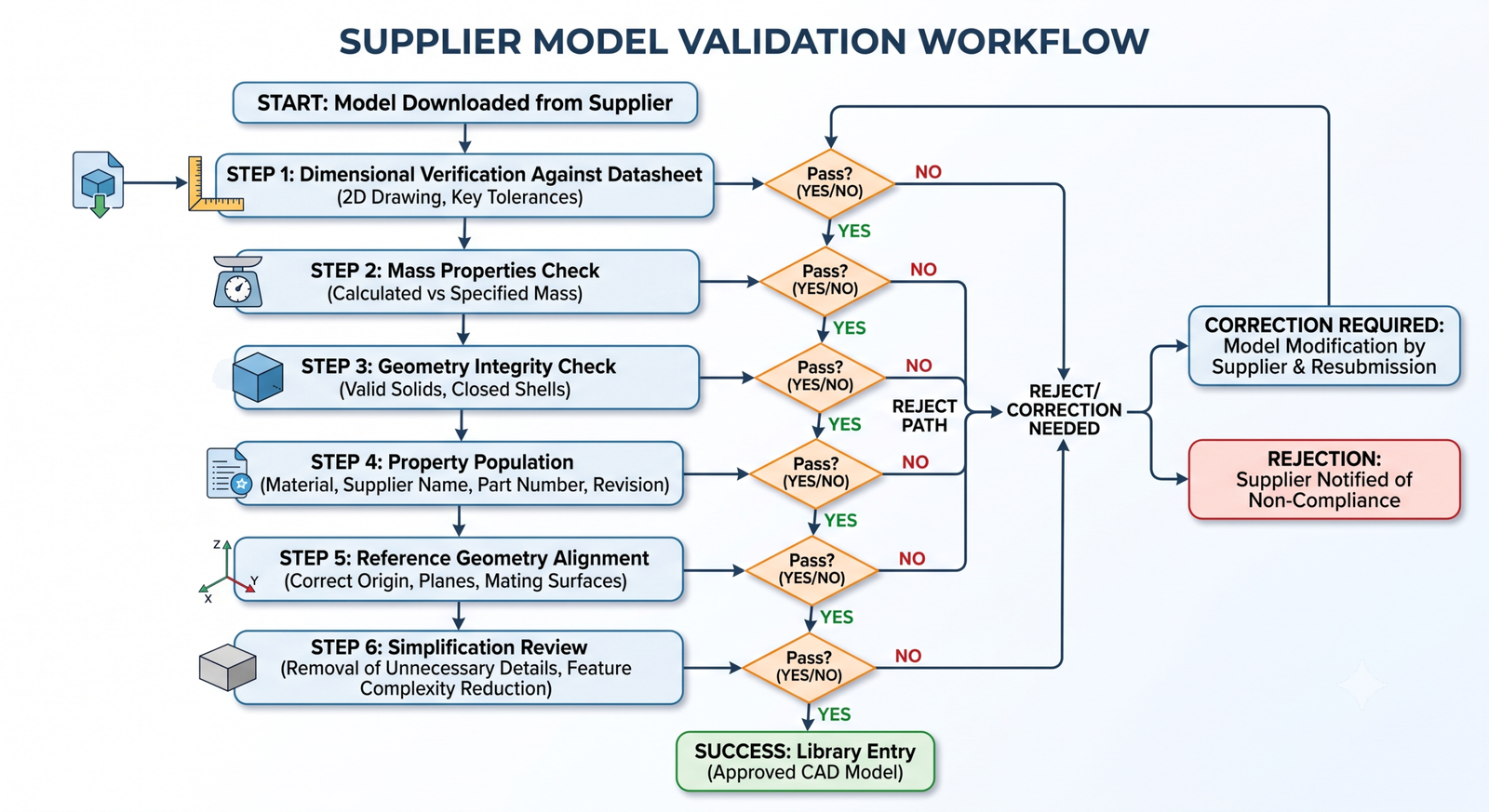
Every model that enters the standard hardware library from an external source must pass through a validation workflow before it is available for use. This workflow is not optional. Its purpose is to prevent library contamination from supplier models that have incorrect dimensions, missing mass properties, incorrect material assignments, or geometry errors that cause assembly interference problems.
The validation workflow for each supplier model should include the following steps, performed by a designated validator before the model is committed to the library:
- Dimensional verification: Open the model and check its key dimensions against the supplier’s published specification sheet or datasheet. Verify the thread pitch, the bore diameter, the overall envelope, and any critical interface dimensions. A bearing whose bore diameter is wrong by 0.1 mm will cause every assembly that uses it to have an interference error.
- Mass properties check: Verify that the model’s reported mass is consistent with the supplier’s published weight specification. A model with zero mass or obviously incorrect mass has not been assigned material properties, and any assembly that includes it will have incorrect mass calculations.
- Geometry integrity check: Run the CAD platform’s geometry check tool (Check Entity in SolidWorks, Geometry Check in Creo) to verify that the model contains no invalid geometry, non-manifold edges, or zero-thickness faces that would cause assembly or analysis errors.
- Property population: Add all standard custom properties: part number, supplier name, description, material, mass, and any other properties that your team’s BOM requires. A model with empty property fields will produce BOM line items with missing data.
- Reference geometry alignment: Verify that the model’s origin and reference planes are positioned in a way that makes assembly mating intuitive. A bolt whose origin is at the tip of the thread rather than at the head face will be awkward to mate correctly in assemblies.
- Simplification review: Assess whether the model’s geometric complexity is appropriate for its intended use in assemblies. Supplier models sometimes include internal geometry, thread detail, and surface features that are accurate but create enormous file sizes and slow assembly performance. Simplify or defeature before adding to the library if the model will be used in large assemblies.
Building Parametric Fastener Tables in the Library
Rather than downloading and validating individual fastener models for every size that might be needed, a more scalable approach is to build parametric fastener part files with design tables that cover an entire size range from a single model. A single parametric M-series socket cap screw model driven by a design table can produce M3, M4, M5, M6, M8, M10, M12, M16, and M20 configurations from one file, each configuration with the correct dimensions, mass, and properties for that size.
This approach reduces the library file count, ensures dimensional consistency across the size family (since all sizes are derived from the same parametric model), and makes adding a new size trivial (add a row to the design table). The initial investment to build the parametric model and populate the design table for a complete M-series range is two to three hours, after which the entire size family is available indefinitely with no further modeling work.
Tier 4: Custom Standard Components and Sub-Assemblies
Custom standard components are the most company-specific layer of the library and often the most valuable. They are the parts and sub-assemblies that appear repeatedly across your company’s products because they represent solutions to problems that your engineering team has already solved well: a mounting bracket in three sizes, a standard cable clamp, a universal gearbox interface plate, a sensor mounting block that accommodates your standard sensor family. Every time an engineer needs one of these components, they should not be modeling it. They should be dragging it from the library.
Identifying Candidates for the Custom Library
The fastest way to identify candidates for the custom standard component library is to conduct a frequency audit: review the last twelve months of completed designs and identify parts or sub-assemblies that appear in more than one project. Any component that was modeled more than once represents a duplication of effort that a library component would have prevented. High-frequency repeats are the highest-priority library candidates.
A complementary approach is to look at the future product roadmap: which components are likely to be needed across multiple upcoming projects? Building these as library components before the first project that needs them means every subsequent project benefits from the library version rather than the project-specific version.
Building Custom Components for Reuse, Not Just for Use
A component designed for a specific project and a component designed for the library look different from the inside, even if their external geometry is identical. A library component is built with reuse explicitly in mind: named parameters for every dimension that might need to vary between applications, a design table to manage multiple standard configurations, descriptive feature naming that makes the model understandable to any engineer who opens it, fully populated custom properties that feed correctly into any project’s BOM, and a library-standard reference plane convention that makes mating in any assembly intuitive.
Building components for the library takes longer than building them for a single project because of this additional investment in parametric structure, documentation, and configuration. The additional investment is typically 50 to 100 percent more time than a project-specific part would require. This additional time is recovered the first time the component is reused from the library rather than rebuilt from scratch.
The Review and Approval Process for Custom Components
Custom components entering the library must pass through a review process that verifies their quality before they are available to the team. The review should be performed by a designated reviewer (the CAD manager, a lead engineer, or a rotating review role depending on team size) and should check:
- Is the part built to the library modeling standard? Named parameters, logical feature tree, correct template used as the starting point?
- Are all custom properties populated correctly and consistently with the library’s naming conventions?
- Does the design table (if applicable) include all expected configurations and have all configurations been verified to rebuild correctly?
- Is the reference geometry (origin planes, mating faces) positioned according to the library standard so the part mates correctly in any assembly?
- Is the model simplified appropriately for assembly use? No unnecessary internal geometry, no thread detail that creates performance problems in large assemblies?
- Is the component documented in the library register with its intended use, size range, applicable standards, and the contact for questions?
Library Governance: The System That Keeps the Library Trustworthy
A library without governance is a library with a deadline. It will be useful for a period, degrade gradually as inconsistent contributions accumulate and outdated components go uncorrected, and eventually become too unreliable for systematic use. Governance is what converts a one-time investment in library building into a long-term compounding asset.
The CAD Library Register
Every library component should have a corresponding entry in a library register: a controlled document that records what each library asset is, who is responsible for it, when it was last reviewed, and whether it is current and approved for use. The register does not need to be elaborate. A structured spreadsheet or a simple PLM record for each library component is sufficient for most teams.
Library Register Fields (Minimum Recommended Set) |
The Library Audit Cycle
Schedule a library audit at regular intervals, at minimum annually, and ideally semi-annually for active libraries with frequent contribution. The audit reviews every active library component against the following questions:
- Is this component still being used? Check the PDM usage tracking. Components with zero uses in the past twelve months are candidates for archiving.
- Has the underlying standard, specification, or supplier catalogue changed since this component was added? If yes, update the component or flag for update.
- Has a better version of this component been built as part of a recent project? If yes, evaluate whether the project version should replace or supplement the library version.
- Are there any known issues or limitations that have been discovered since this component was approved? Document them in the register.
- Is the component’s documentation current? Custom properties, notes, and library register entry should reflect the component’s current state.
Components that fail the audit are not necessarily deleted. They are moved to a review queue, corrected by their owner, and re-approved before being restored to active status. Components that cannot be corrected (because the underlying design is superseded or the responsible owner has left the organization) are deprecated, marked clearly as not for use in new projects, and eventually archived.
Contribution Workflow: Making It Easy to Add, Hard to Contaminate
The governance paradox in library management is that the stricter the contribution process, the fewer contributions the library receives, but the more trustworthy each contribution is. The looser the contribution process, the more contributions the library receives, but the less trustworthy each one is. The solution is to make the correct contribution path easy and the incorrect path difficult: streamline the review process so it takes hours rather than days, and configure the PDM system so that engineers cannot add files to the library folders without triggering the review workflow.
In practice, this means providing engineers with a contribution template: a checklist of what a library-ready component must include, a naming convention guide, and a simple submission process (check the file into a specific PDM folder that triggers the review workflow). The reviewer is notified automatically, completes the review against the checklist, and either approves the component (moving it to the active library) or returns it to the contributor with specific feedback on what needs to change.
Read related article on: Multi-Body Modeling Techniques Every CAD Designer Should Know
PDM Integration: Making the Library the Path of Least Resistance
The most technically complete CAD library in the world delivers zero value if engineers cannot easily find and use what is in it. Library accessibility is a design decision, not just a storage decision. How the library is connected to the CAD environment, how engineers discover what is available, and how quickly they can go from knowing they need a component to having it in their assembly determines the actual usage rate of the library and therefore the return on the investment that built it.
Configuring the PDM Vault as the Library Source
In a PDM-managed environment, the library should live in the vault as a set of controlled, read-only folders that every engineer has access to through the PDM client. Engineers should never need to navigate outside their CAD tool to find library components: the library folder appears in the CAD task pane or design library panel, and components can be dragged directly from it into the active assembly.
SolidWorks PDM Professional integrates directly with the SolidWorks Design Library panel, making library files in the vault accessible through the same interface used to access local library files. Creo Windchill provides a similar integration through the Windchill workspace. Autodesk Vault integrates with the Inventor Place Component dialog. Configuring these integrations correctly is the single highest-return configuration task in library deployment, because it removes all friction between knowing a library component exists and using it.
Search and Discoverability: Engineers Must Be Able to Find What Exists
An inaccessible library component is a wasted investment. Every component in the library must be findable through search, not just through navigation. This requires populating the library register and component metadata with the terms engineers actually use when searching: not just the formal standard name of the component but the common names, abbreviations, and synonyms that engineers type into the search box at two in the afternoon when they need a part fast.
PDM systems with full-text search across custom properties provide the most comprehensive discoverability. Supplement the search capability with a visual catalog: a simple PDF or web-based gallery of library components organized by category, with thumbnail images and key specifications visible without opening the CAD file. Engineers browsing for a solution to a design problem often do not know the exact name of what they need. A visual catalog enables discovery by recognition in a way that text search alone cannot.
The Library Landing Page Concept
For larger teams, consider building a library landing page: an internal intranet page or shared document that serves as the human-readable index of the entire library. It lists every active library tier, provides links to the relevant PDM folder for each tier, includes the library register for reference, shows any recent updates or additions, and lists the CAD manager’s contact for library questions and contributions.
This landing page converts the library from a set of folders in a vault into an explicit team resource with a visible home. Engineers who know where the library landing page is and visit it regularly will use the library more consistently than engineers who must remember which PDM folder path contains the asset they need.
Library Component Lifecycle: When to Update, Fork, or Retire
Every library component has a lifecycle that does not end at the moment it is approved and made active. Components evolve as designs improve, as standards update, as manufacturing processes change, and as the team’s understanding of a problem domain deepens. Managing this lifecycle correctly is what separates a library that improves over time from one that gradually accumulates obsolete versions.
When to Update a Library Component
Update a library component when a better version of the same solution exists: the original had a modeling error, the underlying standard has been revised, or a recent project produced a clearly superior implementation of the same function. Updates should always increment the revision letter, and the previous revision should be archived rather than deleted. Projects that used the previous revision should be tracked in the PDM system so that the engineering team can assess whether those projects need to update to the new library version.
Update decisions that affect widely-used components require communication to the team: a brief notice that library component LIB-MECH-0042 has been revised to revision B, with a summary of what changed and why, and guidance on whether existing projects using revision A need to update. Without this communication, engineers may continue using the revision A version without knowing a better version exists.
When to Fork a Library Component
Fork a library component when a project requires a variant that differs enough from the original to justify a separate library entry but shares enough commonality to warrant starting from the original as a base. A standard mounting bracket that needs a new size range, a standard seal groove that needs a different material specification for a high-temperature application, a standard connector block that needs a modified pinout for a new product platform.
Forking produces two library entries from one original. Both are active, both are governed, and both are documented in the register with a note indicating their relationship. The fork is not a copy of the original that then diverges uncontrolled: it is a deliberate, documented branching of the component’s lineage, with both branches maintained under the library’s governance process.
When to Retire a Library Component
Retire a library component when its underlying function has been superseded by a newer component that does the same job better, when the component is no longer used in new designs and is not expected to be needed in future projects, or when the component was built to a standard that is no longer applicable.
Retired components are not deleted. They are moved to an archived tier in the library with a status marking them as not for use in new projects, but available for reference in projects that used them historically. This archive respects the reality that engineers working on maintenance or warranty issues for older products may need to reference the exact component geometry that was used in the original design, even if that component is no longer appropriate for new work.
The ROI Calculation: Justifying the Library Investment to Leadership
Engineering managers asked to invest in building a CAD library need a return on investment analysis, not just a productivity narrative. The following table provides the framework for building that analysis using your team’s own numbers.
| Activity | Without Library (hrs) | With Library (hrs) | Time Saved per Use | Break-Even at |
| Place a standard fastener in assembly | 0.25 (model from scratch or find file) | 0.02 (drag from library) | 0.23 hrs (92% reduction) | 4.5 uses |
| Add a standard bearing to assembly | 1.5 (download, validate, place) | 0.05 (validated, drag in) | 1.45 hrs (97% reduction) | 1 use |
| Start a new part with correct standards | 0.5 (set up template properties manually) | 0.02 (open template, rename) | 0.48 hrs (96% reduction) | 2 uses |
| Reuse a company-standard bracket | 4 (model from scratch) | 0.1 (drag, configure) | 3.9 hrs (97% reduction) | 1 use |
| Add a boss-and-counterbore feature | 0.5 (sketch, extrude, cut sequence) | 0.05 (drag Library Feature) | 0.45 hrs (90% reduction) | 2 uses |
| Start a new drawing with title block | 0.5 (set up formats manually) | 0.02 (open drawing template) | 0.48 hrs (96% reduction) | 2 uses |
| Library build investment (one component) | N/A | 2-4 hrs (model, validate, document) | N/A | 2-4 reuses to break even |
To calculate your team’s specific ROI, take each activity row, estimate how frequently each engineer on your team performs that activity per month, multiply by the time saved per use, and sum across all engineers and all activities. For a team of eight engineers, the aggregate monthly time saving from a complete library implementation typically ranges from 40 to 120 engineering hours per month, depending on the nature of the work and the starting point of efficiency. At an engineering cost rate of 80 to 150 dollars per hour, this represents a monthly value of 3,200 to 18,000 dollars that the library delivers after breakeven.
The library build investment for a team of eight engineers starting from scratch is typically 80 to 160 hours across the CAD manager and contributing senior engineers, concentrated in the first three months and ongoing at 8 to 16 hours per month for maintenance and expansion. This investment breaks even within the first quarter for most teams and delivers compounding returns every month thereafter as the library grows and usage deepens.
Frequently Asked Questions
Q: What is a reusable CAD library and why does every engineering team need one?
A reusable CAD library is a curated, governed collection of templates, reusable geometry features, standard hardware models, custom standard components, and supplier-provided geometry that engineers can use directly in their designs without modeling from scratch. Every engineering team needs one because the same components, fasteners, bearings, brackets, and sub-assemblies appear repeatedly across projects. Every time an engineer models something that already exists in the library, they are spending time that creates no new value. A library converts that duplicated effort into reuse, typically reducing design time by 30 to 80 percent on the tasks it covers.
Q: What is the most important tier to build first in a CAD library?
Templates are the highest-priority starting point because they affect every file that every engineer creates from the moment they are deployed. A well-built part template, assembly template, and drawing template with correct unit settings, custom property fields, material database links, and pre-configured reference geometry delivers immediate productivity gains to the entire team with no change in workflow. Start with Tier 1 templates, deploy them through the PDM system as the required starting point for all new files, and then build the other library tiers in parallel with ongoing project work.
Q: How do you validate supplier-provided CAD models before adding them to the library?
Run each supplier model through a six-step validation workflow before library entry: dimensional verification against the supplier datasheet, mass properties check against the published weight specification, geometry integrity check using the CAD tool’s geometry analysis function, property population to add all required BOM fields, reference geometry alignment to ensure intuitive assembly mating, and simplification review to remove unnecessary internal geometry that would slow assembly performance. Every step is required. A model that passes five of six checks but fails dimensional verification is still a contaminated library entry waiting to propagate errors across projects.
Q: What is a library feature and how does it differ from a standard part?
A library feature is a reusable geometry pattern that is inserted into an existing part, not a complete standalone part. Examples include counterbored hole patterns, chamfer sequences, standard rib and boss layouts, and groove profiles. A standard part is a complete component that is placed as a whole into an assembly. Library features (called Library Features in SolidWorks, UDFs in Creo, and iFeatures in Inventor) fill the gap between templates and full parts, providing reusable geometry building blocks for engineers who need to apply standard feature patterns to custom parts.
Q: How should a CAD library be governed to prevent quality degradation over time?
CAD library governance requires three mechanisms working together: a quality gate at entry (every new component passes through a review and approval process before becoming active), a library register (a controlled document listing every component’s status, owner, revision, and last review date), and a scheduled audit cycle (at minimum annual review of every active library component against quality and currency criteria). Libraries without all three mechanisms degrade predictably as incorrect components accumulate and outdated components persist. Governance does not need to be bureaucratic, but it must be consistent.
Q: How do you make the CAD library accessible to engineers in their daily workflow?
Configure the library to be directly accessible from within the CAD tool through the platform’s native library panel: SolidWorks Design Library, Creo’s folder browser connected to Windchill, or Inventor’s Content Center. Store library files in the PDM vault in read-only controlled folders that are mapped to this panel. Ensure engineers can search by keyword across component metadata. Provide a visual catalog as a PDF or intranet page for browsing by category. Remove every step between knowing a library component exists and placing it in an active assembly. Each removed friction step increases library usage measurably.
Q: When should a CAD library component be retired versus updated?
Update a library component when a better implementation of the same solution exists: a modeling error is corrected, the underlying standard is revised, or a recent project produced a superior version. Retire a library component when its function has been superseded by a different component, when it is no longer expected to be needed in future designs, or when it was built to a standard that is no longer applicable. Never delete retired components: archive them with a status marking them as not for use in new projects but available for historical reference. This archive supports maintenance and warranty work on products that used the retired component in their original design.
Conclusion:
The most successful CAD libraries in engineering organizations share one characteristic: they are treated as engineering assets by engineering leadership, not as IT infrastructure by the IT department or as side projects by individual engineers. They are funded, maintained, measured, and continuously improved with the same discipline that would be applied to any other capital asset that the engineering team depends on.
The return on that investment is not theoretical. Every hour a library component saves is an hour the team can spend on problems that have not been solved before: new engineering challenges, innovation, customer-specific requirements, and the design work that genuinely requires original thought. A team without a library spends a measurable fraction of its capacity re-solving problems it has already solved. A team with a well-governed library applies that capacity forward.
Start where the return is highest: templates. Build them correctly, deploy them through the PDM system, and watch how much setup time disappears from every engineer’s workflow immediately. Then build the Tier 3 standard hardware library, with proper validation for every entry. Then systematize the reuse of your best custom components as Tier 4 library assets. The library grows from there, one well-built component at a time, each one delivering returns every time it is reused.
Three years into a well-managed library program, most engineering teams report that the library has become one of the most valuable engineering resources they have, rivaling the CAD software itself in its impact on daily productivity. That outcome starts with the decision to build it deliberately rather than letting it grow organically, and with the governance discipline to keep it trustworthy once it is built.
Continue building your engineering efficiency with our guides on CAD file management best practices, design tables for product families, parametric modeling and design intent, and design for assembly principles.
Leave a Reply