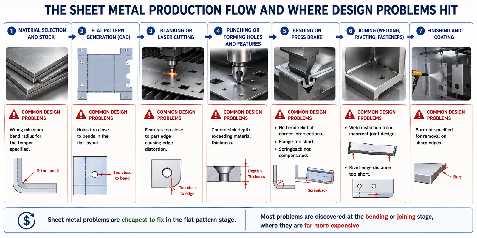
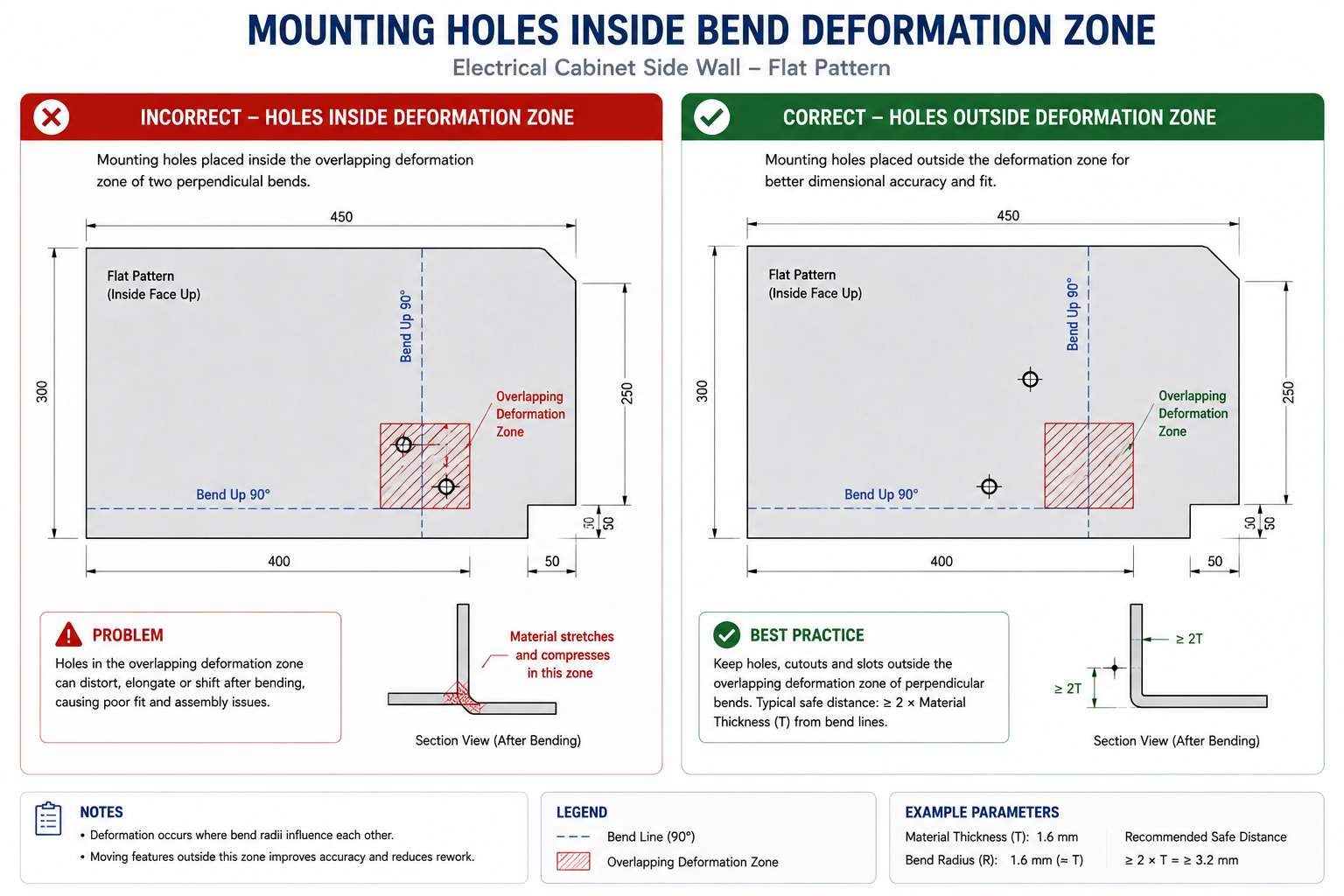
An enclosure had been designed and drawn in about a day. It was a straightforward electrical cabinet: four walls folded up from a base, a bolt-on lid, four mounting holes on each side wall. The designer had worked with sheet metal before and knew the basic rules. What they missed was that two mounting holes sat 8mm from a corner where two bend lines met, squarely inside the deformation zone of both bends at once.
When the flat blanks came back from the laser cutter and went to the press brake, the operator called before making the first bend. Those two holes would distort into ovals on both walls, badly enough that the mating hardware wouldn’t align. The fix took ten minutes in CAD: move the holes 5mm toward the centre of the wall face, outside the deformation zone. But the flat blanks had already been cut, so that first set became scrap, and a new set had to be laser cut from fresh stock. The design change was trivial. The timing of when it was caught was the entire problem.
| Quick answer: Sheet metal design rules are directly tied to the physics of how thin material stretches and compresses during bending. The core ones: keep the bend radius above the material’s minimum, keep holes and features outside the deformation zone near a bend line, add relief notches wherever two bends meet at a corner, and account for springback in the bend angle rather than assuming it away. Every one of these is free to fix in CAD and expensive to fix after the material is cut. |
Read more on 12 Injection Molding Design Mistakes That Drive Up Cost
How Sheet Metal Bending Actually Works
When a press brake bends a sheet, the material on the outside of the bend stretches in tension while the inside compresses. Between the two zones sits a neutral axis where, in theory, material length is unchanged. In practice, that neutral axis shifts toward the inside of the bend as the radius tightens, so the outside surface works harder than simple geometry would suggest.
This is why a minimum bend radius exists: it’s the radius below which the outer surface experiences enough tensile strain to exceed the material’s ductility limit and crack. Different materials have different ductility, so they have different minimum radii, and the same material in a harder temper needs a tighter minimum than it would annealed. Minimum bend radius is typically expressed as a multiple of material thickness rather than an absolute dimension, since the physics scales proportionally with thickness.
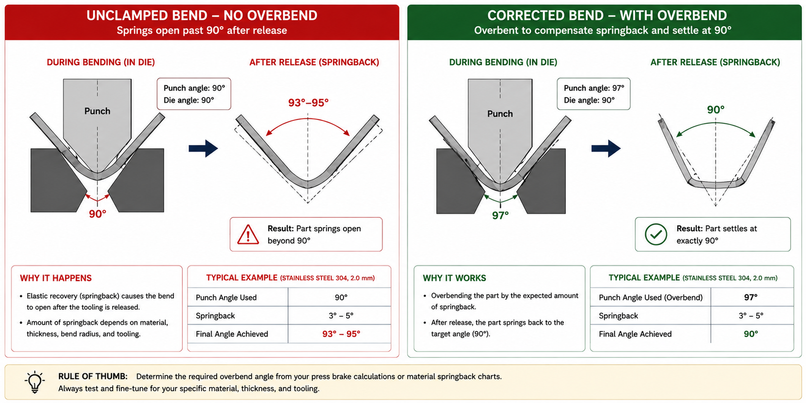
The other phenomenon every sheet metal designer needs to understand is springback: the elastic recovery that happens when bending load is removed. Metal deforms both elastically and plastically during bending. The plastic deformation stays permanent and forms the bend, but the elastic portion springs back toward the original flat shape when the punch lifts.
The part opens slightly beyond the intended angle after the tool releases it. Mild steel at 90 degrees might spring back one to two degrees. Stainless at the same angle might spring back five to ten degrees. High-strength steel might spring back twenty degrees or more. This isn’t a manufacturing defect; it’s predictable behavior that has to be designed into the flat pattern and tooling setup, not discovered as a surprise at first-article inspection.
Minimum Bend Radii by Material and Condition
These values assume bending perpendicular to the rolling direction. Bending parallel to the grain requires a larger radius, particularly in harder steels, following the bending data documented in Machinery’s Handbook’s sheet metal forming section. When in doubt, bend across the grain or confirm the minimum with a bend test sample before committing a production run.
| Material | Condition | Min Bend Radius (x thickness) | Cracking Risk |
|---|---|---|---|
| Mild steel (CR) | Annealed/soft | 0.5x to 1x | Low |
| Mild steel (CR) | Half-hard/work-hardened | 1x to 1.5x | Medium if under-radiused |
| Aluminium 5052 | H32 | 0.5x to 1x | Low |
| Aluminium 6061 | T6 | 2x to 3x | High without adequate radius |
| Aluminium 3003 | H14 | 0.5x | Very low |
| Stainless steel 304 | Annealed | 1x to 1.5x | Medium; springback more of a concern than cracking |
| Stainless steel 316 | Annealed | 1x to 2x | Medium |
| Copper (ETP) | Annealed | 0.5x | Very low |
| Brass (70/30) | Half-hard | 1x to 1.5x | Low to medium |
| Galvanised steel | Same as base steel | Same as uncoated mild steel | Low for base metal; medium for coating integrity |
| High-strength steel (HSLA) | As-rolled | 2x to 4x | High without adequate radius |
Always confirm minimum bend radius with a test bend before production. Real sheet material varies between coils, suppliers, and batches of the same nominal spec. For any critical or unusual material, ask your fabricator to cut two test blanks and form a trial bend before the full production batch is cut. A test bend costs one blank and ten minutes. A full batch of cracked parts costs the material, the laser time, and the press brake time, plus the investigation delay.
Feature Proximity to Bends and Edges
Sheet metal deformation during bending isn’t confined to the exact line where the punch touches the material. The stretched and compressed zone extends outward from the bend line, in both directions, by roughly the material thickness. Features landing inside this zone get pulled, stretched, or torn as the surrounding material moves during forming: holes become ovals, slots tear toward the bend line, carefully positioned mounting features end up in the wrong spot after forming.
The distances below are measured in the flat pattern before forming, not the final formed dimensions. If the flat pattern layout violates them, the feature distorts on the first bend and can’t be corrected afterward without scrapping the part.
| Feature | Min. Distance to Bend Line | Min. Distance to Part Edge | Fix if Feature Must Be Closer |
|---|---|---|---|
| Round hole (punched) | 2.5x thickness + bend radius | 1.5x thickness | Move to flat development away from bend; or punch after forming |
| Slot (punched) | 4x thickness, slot edge to bend line | 1.5-2x thickness, edge to edge | Add a bridge between slot end and bend line; or form first, cut second |
| Notch (open slot to edge) | 3x thickness, notch end to bend line | N/A (reaches the edge) | Add circular relief at notch end, sized at least 1.5x thickness diameter |
| Embossed feature (bead, dimple) | 3x thickness + feature height | 2x thickness | Complete bending before embossing; or locate emboss well away from bend |
| Tab or lance | 2x thickness from any other bend/feature | 1.5x thickness, tab base to edge | Space tabs evenly; avoid tabs within 10mm of corners |
| Louver | 4x thickness to nearest bend | 3x thickness to edge | Locate louvers in flat regions, well away from bends and edges |
The Bend Relief: Small Feature, Large Consequence
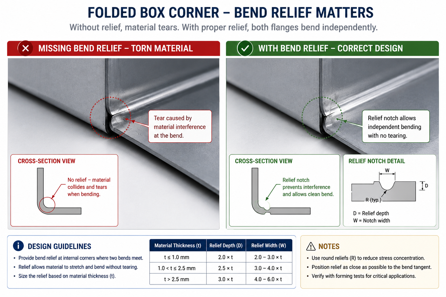
A bend relief is a small notch cut into the flat blank at every location where two bend lines would otherwise meet at an interior corner. Without it, the material at that corner is asked to bend in two directions simultaneously, more than thin sheet material can accommodate without tearing or buckling. The tear propagates from the corner into the adjacent face, splitting the part.
The relief notch gives the material somewhere to go, removing the constrained corner and letting each adjacent flange bend independently. The minimum relief width is typically one to two times material thickness, with the depth extending slightly past the bend line, usually half the thickness, to ensure the bend clears the notch geometry before it begins. Most CAD sheet metal tools generate reliefs automatically during flat pattern creation, but default sizes are sometimes smaller than the actual material and bend radius require. Check the flat pattern geometry, particularly on corners where thin gauge meets a tight bend radius, before the drawing goes for quoting.
Springback: Designing the Angle In Rather Than Out
Springback is one of the most reliably mishandled aspects of sheet metal design, not because it’s complicated but because it’s invisible in a CAD model. A 3D model shows the desired final angle. The springback that happens when the press brake releases the material exists only in the relationship between material, tooling, and process, and it has to be accounted for before the flat pattern is finalised.
The principle is simple: overbend the part by the expected springback angle so it lands at the intended angle once it springs back. A 90-degree bend in mild steel with two degrees of springback needs to be bent to 88 degrees at the punch. The same bend in high-strength steel with twenty degrees of springback needs to be bent to 70 degrees. Springback doesn’t change the final part geometry, since it’s built into the tooling setup, but it does change the punch angle, and that information needs to be documented, not assumed to be zero.
What controls the springback angle:
- Yield strength: higher yield strength means larger elastic recovery and larger springback, why high-strength steels spring back dramatically more than mild steel at the same geometry
- Elastic modulus: springback scales inversely with modulus; aluminium tends to spring back more than mild steel of equivalent yield strength
- Bend radius to thickness ratio: tighter bends have less springback, since more of the deformation is plastic rather than elastic at smaller radii
- Material temper: harder tempers have higher yield strength and therefore more springback than annealed versions of the same alloy
The most reliable way to determine actual springback for a specific batch and geometry is a trial bend on a test piece cut from the actual production material, eliminating the guesswork from published springback factors, which are averages rather than values specific to any one coil.
Flange Length, Hems, and Returns
A flange is the portion of a part bent away from the main body. The minimum usable flange length is set by the press brake tooling: the V-die needs to support material on both sides of the bend line, and the punch needs to form the bend without the material slipping out. Flanges shorter than the tooling’s minimum grip length produce inaccurate, inconsistent bends because the material isn’t properly constrained during forming.
The practical minimum flange length for most setups is three times material thickness plus the inside bend radius. For 2mm mild steel with a 2mm inside bend radius, that’s 3 x 2 + 2 = 8mm minimum. Very thin gauge with tight bend radii can sometimes work with shorter flanges given specialised tooling, but that needs fabricator confirmation, not a design assumption.
Hems: Folding an Edge Back on Itself
A hem folds the sheet edge back onto itself, creating a double thickness at the edge. Hems stiffen an edge that would otherwise flex and eliminate the sharp cut edge that creates a hazard and tear point on thin sheet metal. Open hems fold to a specific radius and leave a gap; closed hems press all the way flat for a solid double layer.
The minimum radius for an open hem is roughly the material thickness. A closed hem needs enough ductility to fold all the way flat without cracking on the outer surface. Closed hems work reliably in annealed mild steel and soft aluminium alloys. They’re not reliable in stainless steel or hard aluminium tempers, where the outer surface cracks during the second fold. Specifying a closed hem on stainless or 6061-T6 will produce a first-article failure requiring either an open hem or an annealed temper for the hem operation, adding a separate heat treatment step.
Joining Methods for Sheet Metal Assemblies
The joining method affects structural performance, appearance, material compatibility, and total cost including labour and equipment.
| Joining Method | Typical Strength | Best Material Combinations | Design Consideration |
|---|---|---|---|
| MIG/MAG welding | Full parent strength achievable with correct procedure | Mild steel to mild steel; stainless (TIG preferred); adapted aluminium wire/gas | Plan joint sequence to minimise heat-induced warping; 0.5-1.0mm root gap for full penetration |
| TIG welding | Higher quality than MIG; suits thin gauges | Thin stainless (below 1.5mm); aluminium; dissimilar metals with correct filler | Slower and costlier than MIG; preferred where weld quality/appearance is critical |
| Spot welding | Shear strength 1-5 kN per spot; lower peel strength | Mild steel; galvanised steel; limited aluminium use | 3x electrode diameter centre-to-centre; min. 8mm edge to spot centre |
| Riveting (solid or blind) | Good shear; lower tension than bolting | Mixed materials with appropriate rivet alloy to avoid galvanic corrosion | Hole tolerance +0.1/-0.0mm; blind rivets need 1.5x body diameter flange clearance |
| Self-clinching fasteners | Typical PEM nut in 2mm steel: 1000-2000 N pull-out | Steel minimum 1.0mm; stainless 1.2mm; aluminium needs specific PEM series | Min. edge distance 3x fastener diameter; min. 3x diameter between fasteners |
| Structural adhesive bonding | Overlap shear 10-20 MPa for epoxy on clean steel | Mixed materials, glass-to-metal, composite-to-metal | Bond line 0.1-0.5mm optimal; joint must load the adhesive in shear, not peel |
| Folded interlocking seams | Comparable to light spot welding for non-structural panels | Same material both sides; thin gauge ductile materials | Interlocking tabs give square alignment; common for HVAC and light enclosures |
Weld Distortion: The Problem Every Sheet Metal Designer Underestimates
Welding puts intense, localised heat into sheet metal, and as it dissipates, differential contraction of the heated and cooled zones warps the surrounding material. Thin gauge sheet, with low thermal mass, heats and cools quickly and unevenly, so this warping can be severe enough to destroy an assembly’s dimensional accuracy if the weld sequence and joint design aren’t planned in advance.
Symmetric joint placement, distributing welds evenly rather than concentrating them on one side, reduces net distortion because shrinkage in one location partly cancels shrinkage in a symmetric one. Intermittent welds, short runs with gaps, reduce total heat input for a given joint length. Back-stepping, welding short segments in the opposite direction to the overall weld path, keeps the heat zone moving away from already-welded material. None of these need special equipment, just a weld sequence plan made during design, not discovered on the weld table when the third weld pulls the first two out of square.
Eight Common Sheet Metal Design Mistakes and Their Fixes
Every one of these is a design decision correctable in CAD before the material is cut.
| Mistake | Process Impact | Fix |
|---|---|---|
| Bend radius tighter than material minimum | Material cracks on the outside of the bend; fails at first forming attempt | Specify radius at or above the material/temper minimum; confirm with supplier for unusual materials |
| Holes too close to a bend line | Round holes distort oval; slots tear toward the bend | Move holes at least 2.5x thickness plus bend radius from the bend line; or punch after forming |
| No bend relief at corner intersections | Material tears at the corner; becomes a stress concentration and splits | Add relief notch of at least 1x thickness width at every corner intersection |
| Flange too short to grip in press brake | Tooling can’t control the flange; bend angle inaccurate and inconsistent | Minimum flange = 3x thickness plus bend radius |
| Springback not compensated in bend angle | Part springs open; specified angle not achieved; assembly interference | Design the bend angle to account for expected springback; verify with a test bend |
| Countersink depth exceeds material thickness | Punch breaks through the far face; hole becomes a conical tube | Countersink depth under 60% of material thickness; use a low-profile fastener for thin gauge |
| Mixed material gauges in one flat pattern | Poor nesting efficiency; two blanking operations; distortion risk | Design a single-gauge flat pattern; join separate-gauge parts during assembly if needed |
| Tab-and-slot clearance too tight or too loose | Too tight: can’t assemble without force. Too loose: slop in the joint | Slot width = tab thickness + 0.2mm laser-cut; +0.3-0.4mm punched; verify with first-article trial |
Worked Examples
The cabinet with holes in the deformation zone: The electrical cabinet from the opening had two mounting holes 8mm from a corner where two perpendicular bends met. For 2mm mild steel, the deformation zone extends approximately 2.5 times thickness plus bend radius from each bend line, 2.5 x 2 + 2 = 7mm here. The holes at 8mm were marginally outside the zone for a single adjacent bend considered alone, but the corner involved two bends approaching from perpendicular directions, and the combined zones overlapped at the hole locations.
Moving the two holes 5mm further toward the centre, to 13mm from the nearest bend line, placed them well outside both individual and combined deformation zones. The mating component had slotted holes, so the shift was absorbed without any change to the mating part. The first set of already-cut blanks was used for a distortion test, confirming the expected oval distortion at the original position. The second set, cut with corrected positions, formed cleanly. The fix itself was five minutes in CAD; the cost was the scrapped first batch, and the lesson: check every hole against the minimum distance-to-bend rule before the drawing goes for cutting.
The stainless panel with springback on the first bend: A 304 stainless control panel had two 90-degree bends forming a U-channel profile. The flat pattern and bend line locations were correct, but the drawing didn’t specify springback compensation, since the designer assumed the operator would handle it during setup. Stainless 304 in 2mm gauge at a 4mm inside bend radius has roughly 5 to 7 degrees of springback.
The operator initially set the brake to 90 degrees as drawn, got parts sitting at 95 to 97 degrees, and corrected by trial-and-error to roughly 84 degrees on the first piece, but the correction wasn’t documented or passed to the next shift, so the second batch formed at the uncorrected angle and failed inspection.
The drawing was revised with an explicit forming note: bend to 84 degrees at punch for a 90-degree finished angle, verify with protractor after forming the first piece. The compensation angle came from the fabricator’s first-article experience rather than a generic table, since batch and tool condition both affect the exact value. The second batch formed correctly, and treating springback as a documented design parameter rather than an operator skill eliminated the root cause.
Frequently Asked Questions
What is the minimum bend radius for sheet metal and why does it vary by material? It’s the smallest inside radius formable without cracking the outer surface, and it varies because different metals have different ductility. A highly ductile material like annealed copper bends to half its thickness or less without cracking. A hard material like 6061-T6 aluminium needs two to three times its thickness minimum, since low ductility means the outer surface hits fracture strain at a much gentler bend angle. The same alloy in a softer temper, 6061-O, is far more ductile and bends much tighter. Always identify both alloy and temper when specifying a minimum radius.
Why do holes need to be so far from bend lines? Material in the deformation zone on both sides of a bend line stretches on the tension side and compresses on the compression side, extending outward roughly 2.5 to 3 times the material thickness. Any feature within that zone distorts along with the surrounding material: a round hole becomes an oval, a slot tears toward the bend line. The most practical fix when a functional feature must sit closer than the minimum is to cut or punch it after forming, so the material has already completed its deformation before the feature is introduced.
What is a bend relief and when is it necessary? A bend relief is a small notch cut into the flat blank wherever two bend lines would otherwise meet at an interior corner. Without it, the corner material is constrained in two directions simultaneously during forming and tears or buckles as each flange tries to bend independently. It’s necessary at every folded corner of a box or enclosure. Typical relief size is one to two times material thickness in width, with depth extending just past the bend line. Verify default CAD-generated relief sizes against the actual material and bend radius before releasing the drawing.
How do I design for springback without knowing the exact material properties? Design with a nominal compensation based on material family and temper, then verify and adjust on the first-article part. For mild steel, one to two degrees at a 90-degree bend. For stainless 304, four to eight degrees. For high-strength steel, fifteen to twenty-five degrees, treating the first article as a calibration exercise. Put the compensation angle on the drawing as a forming note so the calibrated value transfers into the work instructions regardless of who runs the job.
When should I use welding versus mechanical fastening for a sheet metal assembly? Use welding when the joint needs to be permanent, sealed, or load-bearing across its full area, and the materials are weldable. Use mechanical fastening when the assembly must be field-serviceable, the materials aren’t weld-compatible (steel to aluminium), weld heat distortion would compromise accuracy, or production volume doesn’t justify setting up a weld operation. Many assemblies combine both: structural welds at primary load-bearing corners and self-clinching fasteners for component attachment points that may need future access. Make this decision during design, not at the fabricator, since flange widths, rivet spacing, and fastener hole sizes all need to be in the drawing.
How tight a tolerance can sheet metal fabrication actually hold? Standard press brake bending holds angle tolerances of plus or minus one to two degrees and linear tolerances on bent dimensions of plus or minus 0.5mm to 1.0mm. Laser-cut or punched flat features hold plus or minus 0.1 to 0.25mm on hole positions, depending on equipment and gauge.
Note that a bent dimension’s tolerance isn’t the same as a cut dimension’s: a hole positioned at plus or minus 0.1mm in the flat may vary by plus or minus 0.5mm relative to a flange edge after forming, due to springback and material variation. For assemblies where multiple bent dimensions stack together, run a stack-up analysis against the press brake’s actual capability.
Key Takeaways
Every bend in a sheet metal part starts as a straight line in a flat pattern. Every hole starts as a circle. Every notch, tab, and slot has a specific position in that flat layout determining whether the part forms correctly. Features positioned correctly in the flat pattern form correctly. Features that violate the proximity or geometry rules produce first-article failures that are always cheaper to catch in CAD than on the shop floor.
Keep the bend radius above the material minimum. Keep holes and features outside the deformation zone of adjacent bends. Add bend relief at every corner where two bends intersect. Specify springback compensation on the forming note for stainless and high-strength materials. Design flanges long enough for the press brake tooling to grip. Choose a joining method during design, not at the fabricator. These are the habits that turn a drawing into a part that comes back from the shop matching the CAD model, rather than a part that comes back with a call from the operator asking what to do about a feature that didn’t form the way the drawing shows.
Leave a Reply