| 60% faster design cycles reported by organisations adopting modern parametric CAD workflows (Shalin Designs, 2026) 70% of engineering firms with under 50 engineers excluded from enterprise CAD pricing, driving open-source parametric adoption 2026 AI-assisted parametric generation now available in ANSYS, Fusion 360, CATIA, and Creo as a standard workflow feature |
Introduction:
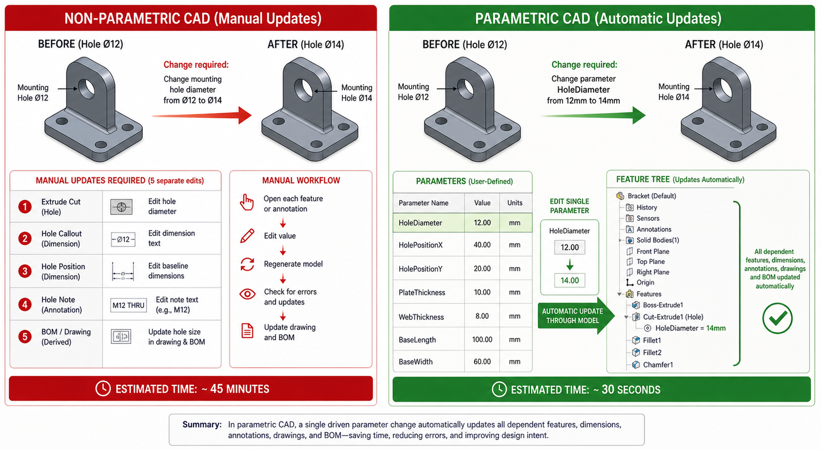
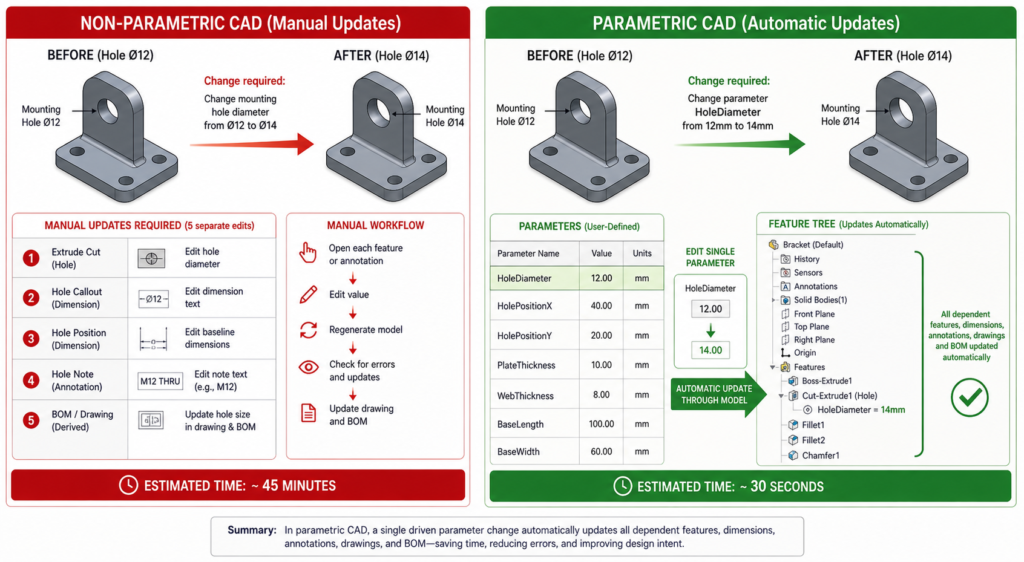
Picture this. A product engineer needs to increase a shaft diameter by 3mm across an entire product family. In a non-parametric CAD environment, that means opening each file, finding every feature that references that diameter, editing it manually, checking that nothing else broke in the process, regenerating the drawing views, and repeating the whole sequence for every variant in the family.
In a well-built parametric CAD model, the engineer changes one value in a design table. The entire part family updates. Every drawing view regenerates. The BOM reflects the new dimensions. The process takes two minutes instead of two days.
That gap, between a design environment that fights your changes and one that anticipates them, is the core reason parametric design in CAD has become the standard approach in manufacturing-focused product development. This guide explains what parametric design actually is, how it works technically, why it matters deeply for manufacturing, and how AI is beginning to extend its capabilities further in 2026.
| Quick answer: Parametric design in CAD is a modeling method where geometry is controlled by parameters and relationships rather than fixed dimensions. Change a parameter and the entire model, its drawings, and its configurations update automatically. It matters for manufacturing because it encodes design intent and manufacturing constraints directly into the model, making design changes fast, controlled, and consistent. |
What Is Parametric Design in CAD? The Clear Explanation
The word parametric comes from parameter, meaning a variable that controls something else. In parametric CAD modeling, those variables are dimensions, angles, radii, counts, and relationships between features. They do not just define the size of the model. They control it.
The Three Pillars of Parametric Design
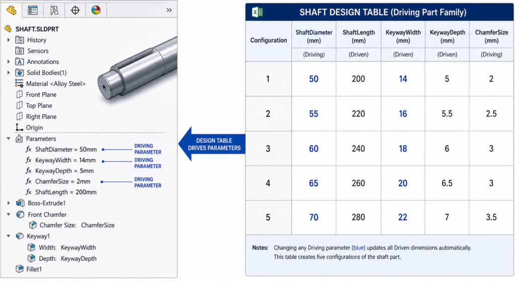
- Parameters: Named variables that drive dimensions. ShaftDiameter = 50mm. BoltPCD = 120mm. WallThickness = 3mm. These can reference each other: FlangeOD = ShaftDiameter x 2.4. Change ShaftDiameter and FlangeOD updates automatically.
- Constraints: Rules that govern geometric relationships. A hole is always concentric with the boss around it. A fillet is always tangent to the two faces it connects. A pattern always maintains equal spacing. Constraints preserve design intent when dimensions change.
- Feature history: The model is built from a sequence of features, each depending on what came before it. An extrude references a sketch. A fillet references the edge created by the extrude. A hole references the face created by the fillet. This parent-child chain is the feature tree, and it is what makes the model intelligent.
When you change a parameter, the solver walks the feature tree from the point of change forward, recalculating every dependent feature in sequence. The result is a model that updates fully and correctly rather than one where you chase broken references through fifty features for the rest of the afternoon.
Design Intent: The Concept That Separates Parametric from Everything Else
Design intent is the engineering reasoning behind the geometry. A flange diameter that is always twice the shaft diameter because that ratio satisfies the stress requirement. A mounting hole pattern that is always symmetric about the part centreline because the assembly requires it. A wall thickness that is never less than 2.5mm because the injection moulding process demands it.
In a traditional 2D drawing or a direct-modeled 3D file, design intent lives in the engineer’s head. When that engineer leaves, the intent goes with them. In a well-built parametric design, the intent is encoded in the model. The relationships and constraints are readable, auditable, and editable by the next engineer who works on the file.
| Why this matters: A parametric design model is not just a shape. It is a specification. It contains not only what the part looks like but the engineering reasoning that produced it. That is what makes it a reliable manufacturing asset rather than a snapshot that becomes obsolete the moment the design changes. |
Parametric vs Direct Modeling: Which One and When
One of the most common questions engineers ask when exploring CAD approaches is how parametric modeling compares to direct or explicit modeling. The honest answer is that they serve genuinely different purposes, and knowing when to use each is a judgment call that experienced CAD engineers develop over time.
| Factor | Parametric CAD Modeling | Direct (Explicit) Modeling |
| How geometry is defined | Driven by parameters and relationships | Pushed and pulled directly by hand |
| Design intent storage | Captured in feature tree and constraints | Not stored, only geometry exists |
| Handling design changes | Edit a parameter, model updates itself | Manually redraw affected geometry |
| Part families | One master model, many configurations | Separate file for each variant |
| Downstream drawing updates | Views regenerate automatically | Views must be redrawn or manually fixed |
| Collaboration | Parameters are readable and auditable | No history, hard to understand intent |
| Best for | Products with design iterations | Quick concept models, scan data |
| Learning curve | Steeper, requires planning upfront | Faster to start, harder to manage later |
| Manufacturing output | Consistent, revision-controlled | Can drift without strict file management |
When Direct Modeling Makes More Sense
Direct modeling is genuinely better in specific situations. When you receive a STEP file from a supplier with no feature history and need to modify geometry quickly, pushing and pulling faces directly is faster than trying to import a feature tree that does not exist. When you are working on a pure concept model that will be thrown away and rebuilt, the time investment in building a parametric model is wasted. When you are working with geometry generated by topology optimisation or a 3D scan, direct tools handle organic shapes better than a feature tree.
Most professional manufacturing-focused CAD tools now offer both approaches in the same environment. Autodesk Fusion 360 and Siemens NX allow you to switch between parametric design history and direct editing depending on what the task requires. This hybrid approach is one of the CAD design trends gaining the most traction in 2026.
Why Parametric Design Matters for Manufacturing: The Real Reasons
Engineers who have only worked in parametric CAD sometimes underestimate how much the modeling approach matters downstream. Parametric modeling for manufacturing is not just about design convenience. It has direct, measurable consequences for what happens at the machine, at the inspection table, and during engineering change management.
| Manufacturing Benefit | What Parametric Design Does | Real Impact |
| Design for Manufacturability | Parameters encode manufacturing constraints | Undercuts, tool access, wall thickness enforced at the model level |
| Part family management | One master model drives all variants | A family of 20 bracket sizes from one parametric file, not 20 separate models |
| Rapid design iteration | Change a dimension, everything updates | Engineering teams at Autodesk report up to 60% faster design cycles |
| Tolerance management | Driven dimensions propagate to drawings | Tolerances remain consistent across all drawing views automatically |
| CAM toolpath reliability | Geometry is clean and feature-based | CAM software reads parametric geometry more reliably than direct-modeled meshes |
| Supplier collaboration | Configurations exported as separate derived files | Supplier gets the correct variant without access to the full design intent |
| Engineering change management | Change is traced through the feature tree | Auditors can see exactly what changed and why between revisions |
| Revision control | Parameters log what drove each design version | Full traceability from concept through production release |
Design for Manufacturability Built Into the Model
The most powerful manufacturing application of parametric design is encoding Design for Manufacturability rules directly as driven constraints. A minimum wall thickness of 2.5mm for injection moulding is not a note on a drawing that a designer might miss. It is a driven dimension that the model cannot violate. A minimum internal corner radius for a machined pocket is not a guideline in a manufacturing specification document. It is a constraint that prevents the feature from being created without it.
This approach fundamentally changes when DFM violations are caught. Instead of discovering at tooling review that a pocket cannot be machined with available cutters, the parametric design constraint flags the issue the moment the engineer tries to create a feature that violates it. The cost of catching a DFM issue in the CAD model is essentially zero. The cost of catching it after tool steel has been cut is measured in thousands.
Managing Part Families Without Chaos
Most manufactured product lines are not single parts. They are families. A pump impeller in five sizes. A fastener in twelve diameter and length combinations. An enclosure in three form factors. Without parametric design, each variant is a separate file with its own maintenance burden. Change a shared feature and you have changed it in one file out of twelve.
With a parametric design master model and a design table, all variants live in one file. The design table drives every variant from a single spreadsheet. When a change is needed, it is made once and propagates everywhere. This approach reduces file management overhead, eliminates version drift between variants, and makes engineering change management tractable at scale.
Reliable CAM Integration
Computer-Aided Manufacturing software reads geometry to generate toolpaths. The quality of that geometry directly affects toolpath reliability. Parametric design models built on clean feature history produce well-defined, mathematically precise geometry with clear face relationships. Direct-modeled or imported geometry often contains small gaps, overlapping surfaces, or undefined edge conditions that cause CAM software to fail or produce incorrect toolpaths.
Manufacturers who have moved their design process to parametric CAD consistently report fewer toolpath errors and faster setup time in their CAM workflows. The geometry the machinist receives is trustworthy because it was built with manufacturing intent, not just visual appearance.
How Parametric CAD Modeling Works: Step by Step
Understanding the process of building a proper parametric model makes the difference between a model that is a joy to modify and one that explodes the moment someone changes a dimension. Here is the sequence that experienced CAD engineers follow.
Step 1: Plan the Model Before Opening the Software
The single highest-leverage habit in parametric CAD is spending time before modeling to understand the design intent. Which dimensions are independent drivers? Which are derived from others? What relationships must always hold true regardless of size? What manufacturing constraints need to be encoded?
Sketch this out on paper. Define the parent-child relationships between features. Identify which sketch elements will be constrained and which will be driven. Engineers who skip this step build parametric design models that work for the first design configuration and break immediately when the second change request arrives.
Step 2: Create Fully Constrained Sketches
Every sketch in a parametric model should be fully defined before extruding. A sketch with open degrees of freedom is a model that can drift unpredictably when a parent feature changes. Fully constrain every sketch with dimensions, geometric constraints (vertical, horizontal, tangent, coincident, equal), and relationships to part geometry or reference planes.
Named dimensions in sketches become accessible as design parameters. Name them meaningfully from the start: BoltHoleDiameter, FlangeRadius, WebThickness. A model where every dimension is called Dim1@Sketch3 is a model that no engineer other than the original author can work with efficiently.
Step 3: Build Features in Logical Dependency Order
The feature tree is a directed dependency graph. Every feature that references geometry from another feature is a child of that feature. If the parent changes, the child recalculates. If the parent is deleted, the child fails.
Build features in the order that reflects their physical and logical dependency. Base geometry first. Material-adding features next. Material-removing features after that. Finishing features such as fillets and chamfers last. This order means that changes to early features cascade naturally through later ones rather than creating broken reference chains.
Step 4: Use Global Variables and Equations
Global variables are parameters that live above the feature tree and can be referenced by any sketch or feature in the model. FlangeOD = ShaftDiameter x 2.4. BoltPCD = FlangeOD – 20mm. WallThickness = MAX(2.5mm, HoleDepth / 10).
Using equations and global variables rather than entering raw numbers into every dimension is what makes a parametric model genuinely intelligent. Change ShaftDiameter and every dimension that references it, directly or through a chain of equations, updates correctly. Enter 50mm into every dimension separately and you have a brittle model that requires manual attention every time any dimension changes.
Step 5: Create Configurations and Design Tables
Once the master model is built and fully parametric, configurations allow you to create named variants without duplicating files. A design table drives configurations from a spreadsheet, specifying the parameter values for each variant. SolidWorks, Creo, and NX all support design tables natively.
A well-built design table is the manufacturing team’s best friend. It clearly documents every variant, the parameters that define it, and the relationships between them. It is also the input that AI tools are beginning to use for automated variant generation in 2026, where functional performance criteria drive parameter selection rather than the engineer specifying every value manually.
Parametric Design in Manufacturing: Industry Applications
The applications of parametric design in CAD vary significantly by industry, but the underlying principle is the same across all of them: encode the engineering intent that drives the geometry, and the model becomes a manufacturing asset rather than a frozen snapshot.
| Industry | How Parametric Design Is Used | Manufacturing Benefit |
| Automotive | Body panels, powertrain components, chassis variants | Single parameter drives roof height across all trim levels |
| Aerospace | Airfoil profiles, structural ribs, fastener patterns | Tolerance chains managed parametrically across hundreds of parts |
| Consumer products | Enclosure families, injection-moulded housings, ergonomics | One master enclosure model generates XS, S, M, L, XL variants |
| Medical devices | Implant sizing series, surgical instrument families | Regulatory compliance parameters locked, size driven by design table |
| Industrial machinery | Conveyor frames, pump housings, gearbox variants | Customer specification drives model directly, reduces custom quoting time |
| Architecture / AEC | Structural member sizing, parametric design facade panels | Engineering changes propagate to fabrication drawings automatically |
| Additive manufacturing | Lattice structures, topology-optimised geometry | AI-generated parametric design lattice adapts density to local stress field |
Real Example: A Pump Impeller Family
A pump manufacturer designs a centrifugal impeller in one nominal size using fully constrained parametric CAD. The key design drivers are: impeller OD, number of vanes, vane angle, inlet diameter, and outlet width. All other dimensions are derived from these five through equations that capture the hydraulic design rules.
From this single master model, a design table generates the full product range: eight impeller diameters from 200mm to 500mm, all hydraulically scaled, all with correct vane geometry, all with manufacturing-ready tolerances applied parametrically. The drawing package for all eight sizes is produced automatically from one drawing template referenced to the master model and design table.
A customer specifies a non-standard impeller diameter for a specialist application. The engineer opens the design table, adds a new row, enters the target diameter, and derives the other parameters from the hydraulic equations. A new compliant geometry is generated in minutes. The same process without parametric CAD would take days of manual drafting and checking.
Parametric CAD Software for Manufacturing: Honest Comparison
Choosing the right parametric CAD software for a manufacturing context depends on your industry, team size, budget, and the complexity of the design families you need to manage. Here is a clear breakdown of the main options in 2026.
| Software | Developer | Parametric Approach | Best Industry Fit | AI / Future Features |
| SolidWorks | Dassault | Feature-based, history tree | Mfg, consumer, medical | AI design suggestions, topology opt |
| Creo Parametric | PTC | Fully parametric, relations | Aerospace, defence | Generative design, model-based def |
| Fusion 360 | Autodesk | Parametric + direct hybrid | SME, product design | AI mesh-to-parametric, cloud collab |
| CATIA | Dassault | Knowledge-based parametrics | Automotive, aerospace | AI-driven rules, 3DEXPERIENCE |
| Inventor | Autodesk | Feature-based, iLogic rules | Industrial, machinery | Interop with Fusion, cloud PDM |
| NX (Siemens) | Siemens | Synchronous + history-based | Automotive, heavy industry | AI geometry healing, digital twin |
| FreeCAD | Open source | Constraint-based parametric | SME, indie engineers | Active community, Python scripting |
The Open-Source Option: FreeCAD
FreeCAD has matured significantly and is a genuine option for independent engineers and small manufacturers who cannot justify commercial licensing costs. Its constraint-based parametric design modeling is conceptually identical to commercial packages. The learning curve is real, the community documentation is extensive, and the Python scripting interface is powerful for automation.
The honest limitation is stability on complex models and the absence of the integrated CAM, simulation, and PDM ecosystems that commercial tools provide. For standalone part design with export to a separate CAM or analysis tool, FreeCAD handles the job. For full integrated product development workflows, commercial options remain significantly more mature.
How AI Is Changing Parametric Design in 2026
Artificial intelligence is not replacing parametric CAD modeling in 2026. It is extending it. The parametric model is the structure that gives AI-generated geometry meaning, editability, and manufacturing relevance. Without parametric design architecture, AI-generated shapes are meshes: visually interesting but impossible to modify or manufacture reliably.
AI-Assisted Parametric Generation
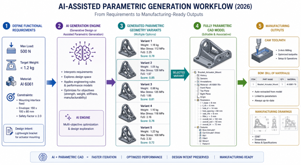
Tools in ANSYS, CATIA, and Fusion 360 now offer assisted parametric generation where engineers define functional criteria: maximum load, target mass, material cost envelope, and manufacturing process. The AI generates multiple parametric design geometry variants, each meeting the constraints, each fully editable in the feature tree.
Backflip AI, which emerged from stealth in early 2025, converts 3D scan data directly into fully parametric CAD models. A scanned legacy part, previously locked as a mesh with no design intent, becomes a feature-based parametric model that can be modified for manufacturing without rebuilding from scratch. This solves one of the most persistent pain points in reverse engineering workflows.
Real-Time DFM Analysis Driven by Parametric Data
Digital manufacturing platforms like Autodesk Fusion and Fictiv now analyse parametric CAD geometry in real time and return DFM feedback before the model is even released for review. Wall thickness violations, unmachineable features, insufficient draft angles for injection moulding, and tolerance combinations that cannot be achieved at the specified process are all flagged at the design stage rather than the production stage.
This capability works significantly better with parametric models than with imported dumb geometry because the solver can read the design parameters, not just the resulting shape. A parametric wall thickness that reads 2.1mm triggers a DFM alert. A wall that appears 2.1mm thick in an imported mesh without parameter metadata may not.
Digital Twins Built on Parametric Foundations
The digital twin concept, where a live computational model mirrors a physical asset and updates as conditions change, relies on parametric architecture. A digital twin of a pump impeller that tracks wear requires a parametric model where wear-related dimensions are driven values that can be updated from sensor data.
Without the parametric foundation, a digital twin is a static 3D representation that cannot be meaningfully updated as the physical asset changes. With it, the digital model reflects the real asset in real time and supports predictive maintenance, performance modelling, and end-of-life assessment.
8 Parametric Design CAD Mistakes That Break Models at the Worst Moment
A parametric model that is built without discipline creates a specific kind of problem: it appears to work perfectly until someone needs to change it, at which point it fails in ways that are difficult to debug and expensive to fix. These are the mistakes that experienced CAD engineers see most consistently in models passed to them from others.
| Mistake | What Goes Wrong | How to Fix It |
| No sketch constraints applied | Model drifts when dimensions change | Fully constrain every sketch before extruding. Use relations, not just dimensions. |
| Feature tree built without order logic | Changing an early feature breaks later ones | Think through the build sequence before modeling. Parent-child dependencies matter. |
| Hard-coded numbers everywhere | Changing one value requires editing every feature | Use global variables or design tables for all key dimensions from the start. |
| No design table for part families | Twenty variants become twenty separate files | Build one master model. Drive all variants from a single spreadsheet design table. |
| Over-constrained sketches | Model throws errors on minor edits | Check for redundant constraints. One fully defined sketch is better than two conflicting ones. |
| Suppressed features not documented | Next engineer unsuppresses wrong features | Add descriptions to every suppressed feature explaining why it exists and when to activate. |
| Parameters not named logically | Dim1@Sketch3 tells nobody anything | Rename every parameter: ShaftDiameter, FlangeThickness, BoltPCD. The model becomes self-documenting. |
| Manufacturing constraints not encoded | Tooling violations discovered at production | Build minimum wall thickness, draft angle, and tool access as driven dimensions from the start. |
The Rebuild Test
A reliable parametric model should survive the rebuild test. Make a significant change to a fundamental parameter, one that affects a large portion of the geometry, and verify that the model rebuilds cleanly without errors, that the drawing views regenerate correctly, and that all configurations update to valid geometry. If the model fails this test, the parametric architecture is fragile and will fail in production use when change requests arrive.
| The hidden cost of bad parametric design models: A parametric model that breaks when modified often gets abandoned in favour of starting again from scratch or, worse, making changes directly in the drawing and bypassing the model entirely. When the model and the drawing diverge, manufacturing gets the wrong information. The cost of a poorly built parametric model is not paid when it is created. It is paid every time someone tries to change it. |
Parametric Design and Design for Manufacturability: The Natural Connection
The relationship between parametric CAD and Design for Manufacturability is not just compatible. It is synergistic. DFM principles translate directly into parametric constraints, and parametric models are the natural environment for encoding and enforcing those principles automatically.
Injection Moulding
Draft angle is mandatory on injection-moulded parts. In a non-parametric environment, the designer applies draft as a finishing step and might miss features. In a parametric model, draft angle is a parameter: DraftAngle = 1.5 degrees. Every extruded feature that requires draft references this parameter. Change the moulding material to one requiring 2 degrees and the model updates every feature simultaneously.
Minimum wall thickness, gate location constraints, parting line geometry, and undercut avoidance can all be parametric constraints. The result is a model that physically cannot be built in a way that violates the moulding process requirements. DFM compliance moves from a review step to a model property.
CNC Machining
Internal corner radii must accommodate the tool radius. Minimum pocket depth-to-width ratios limit tool deflection. Surface finish requirements drive feature sequence and toolpath strategy. These are all parametric constraints that can be encoded as equations: InternalRadius >= CutterRadius + 0.5mm. PocketDepth <= PocketWidth x 4.
When a machinist receives a parametrically constrained model, the geometry has already been validated against machining feasibility. There are no internal sharp corners that require wire EDM when a milling cutter was specified. There are no pockets that are too deep for available tooling. The shop floor operates on geometry that was designed for how it will be made, not just for how it should look.
Conclusion:
Every major manufacturing industry, from aerospace to consumer products, from medical devices to industrial machinery, has converged on parametric CAD modeling as the standard approach for a reason that has nothing to do with software preference. It is the only modeling approach that encodes manufacturing intent in a form that survives design changes.
A direct-modeled part looks exactly the same as a parametric part when both are sitting on a shelf. The difference appears the moment someone makes a change request. The parametric model handles it in minutes. The non-parametric model creates hours of rework, broken drawings, and the real risk that manufacturing gets inconsistent geometry.
In 2026, that difference is being amplified by AI tools that use parametric architecture as the input to generative design, real-time DFM analysis, and digital twin applications. Parametric design in CAD is not becoming more important because of AI. It is becoming more important because every AI workflow that adds value to manufacturing requires a parametric model as its foundation.
Build your models parametrically from the first sketch. Name your parameters clearly. Encode your manufacturing constraints as driven dimensions. Build your part families from design tables. And write your feature trees in an order that any engineer who comes after you can follow.
The best parametric model is one that an engineer who has never seen it before can change confidently on the first day.
Frequently Asked Questions
What is parametric design in CAD?
Parametric design in CAD is a modeling approach where geometry is controlled by parameters and relationships rather than fixed, hand-drawn dimensions. When you change a parameter, every feature, view, and drawing that depends on it updates automatically. The model stores design intent in a feature tree, making it an intelligent, editable record of how and why the part was built, not just what it looks like.
Why does parametric CAD modeling matter for manufacturing?
Parametric CAD modeling matters for manufacturing because it allows you to encode manufacturing constraints directly into the model. Minimum wall thickness, draft angles for injection moulding, tool access clearances, and tolerance relationships can all be driven parameters. When any dimension changes, those constraints still apply automatically. This means fewer DFM violations reaching the shop floor and fewer expensive tooling corrections.
What is the difference between parametric design and direct modeling?
Parametric modeling stores design intent in a history tree with driven dimensions and constraints. Changes propagate automatically. Direct modeling allows geometry to be pushed and pulled freely without a history, which is faster for one-off concepts and imported geometry. Parametric is better for products with multiple design iterations and manufacturing variants. Direct is better for quick concept work or modifying geometry from a scan or external source.
Which CAD software is best for parametric design in manufacturing?
SolidWorks and Creo Parametric are the most widely used for manufacturing-focused parametric design. SolidWorks leads in general manufacturing, consumer products, and medical devices. Creo leads in aerospace and defence where design intent management and model-based definition are critical. Fusion 360 is the strongest option for smaller teams and startups due to its cloud collaboration and accessible pricing.
What is a design table in parametric CAD?
A design table is a spreadsheet embedded in or linked to a parametric CAD model that drives multiple configurations from a single master model. Each row in the spreadsheet defines one configuration by specifying values for the key parameters. A single shaft model can generate 20 size variants from one design table without creating 20 separate files. Design tables are the most efficient tool for managing part families in parametric CAD.
How does parametric design connect to AI and generative design in 2026?
Parametric design is the foundation that makes generative design and AI-assisted CAD possible in 2026. AI tools use parametric relationships to explore thousands of geometry variants that all meet the functional constraints. Tools like Backflip AI convert scanned meshes into fully parametric models. Assisted parametric generation, where an AI creates multiple parametric variants based on functional criteria such as load, weight, and cost, is already available in ANSYS, Fusion 360, and CATIA. The parametric model is what gives AI-generated geometry meaning and editability.
PTC on the principles of parametric modeling in professional CAD’
Leave a Reply