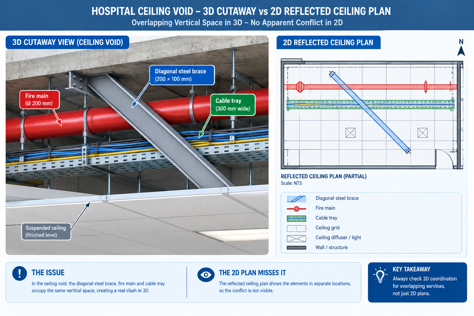
A 340-bed hospital project was six weeks from starting MEP rough-in on its fourth floor when the mechanical contractor’s foreman raised a question during a routine site walk: how was the fire suppression main, already fabricated and staged for installation, supposed to fit through the same 900mm ceiling void as the medical gas piping, the imaging suite’s cable tray, and the structural steel bracing installed two weeks earlier?
The 2D coordination drawings, produced by overlaying each trade’s reflected ceiling plan as flat, semi-transparent PDF layers, had shown no conflict. In three dimensions, the fire main, the cable tray, and a diagonal steel brace occupied the same 400mm of vertical space over an 18-metre run of corridor.
| Quick answer: The conflict had existed since the structural bracing was added five months earlier, passing through three separate 2D drawing reviews because no single 2D overlay showed all three systems at once. This is the problem BIM clash detection exists to solve: three-dimensional conflicts that plan-view drawings, however carefully overlaid, cannot reliably reveal, because a 2D drawing collapses vertical position into a single flat view. Catching a conflict like this during design costs a few hours of model editing; catching it six weeks before fabricated pipe arrives on site costs nine days of schedule float and an emergency design change. |
This article covers the five types of clashes a coordination process needs to catch, the measurable benefits of catching them before construction, the six-stage process that turns separate discipline models into a coordinated design, and a comparison of the tools used to run that process on real projects.
What BIM Clash Detection Actually Does
Clash detection is the automated process of testing the three-dimensional geometry of a federated Building Information Model, a shared model space bringing together individual discipline models from architecture, structure, mechanical, electrical, plumbing, and fire protection, to identify locations where elements from different systems conflict with each other or with a project rule. The output isn’t a design decision; it’s a list of specific, located conflicts, each tied to the exact elements involved and their model coordinates, that the coordination team then reviews, assigns, and resolves.
The distinction between clash detection and clash resolution matters because it defines what the software does versus what the process around it does. The software’s job is exhaustive and mechanical: test every element in one discipline’s model against every element in another’s, according to defined rules, and report every geometric overlap or rule violation, with no judgment about which conflicts matter most.
The coordination team’s job is everything after that: filtering out modelling artifacts that aren’t real conflicts, prioritising the ones that actually threaten schedule or budget, deciding which discipline moves, and confirming the fix worked. Treating the clash report as a finished deliverable rather than the start of a review process is one of the most common reasons coordination programmes underperform.
The Five Categories of Clashes a Coordination Process Should Test For
Relying only on hard-clash geometry testing misses the clearance, sequencing, and rule-based conflicts that cause just as much field disruption as a duct running through a beam.
| Clash Type | Definition | Typical Example | Severity |
|---|---|---|---|
| Hard clash | Two physical elements occupy the same physical space | A structural beam passing through a ductwork run | Critical; cannot be built as drawn |
| Soft (clearance) clash | Elements don’t overlap but violate a required clearance or maintenance zone | A valve installed with less than code-required operating clearance | High; may install but creates an operational or compliance problem |
| Workflow (4D/sequencing) clash | No physical conflict, but construction sequence creates a scheduling or access conflict | A precast panel scheduled before the crane path is clear of scaffolding | Medium to high; causes schedule delay and resequencing |
| Non-collision clash (rule-based) | No overlap or clearance violation, but a business or design rule is violated | A duct routed through a designated clean room | Medium to high; life-safety and compliance rules often critical |
| Duplicate/redundant element clash | The same physical element modelled more than once by two disciplines | A structural engineer and architect both modelling the same slab edge | Low to medium; distorts quantities and coordination confidence |
The Benefits of Clash Detection, Measured Where They Actually Show Up
The case for clash detection is easiest to make concretely: specific, measurable categories of cost and schedule risk shrink when conflicts are caught in the model instead of in the field.
| Benefit | What It Solves | Where It Shows Up | Who Benefits Most |
|---|---|---|---|
| Reduced field rework | Physical conflicts discovered only when a crew tries to install the second system into occupied space | RFIs, change orders, demolition/re-installation cycles during rough-in | General contractors and MEP subcontractors carrying installation risk |
| Schedule certainty | Unplanned stoppages while a field conflict is redesigned and re-procured | Critical path activities in MEP and fire protection rough-in | Schedulers and owners with occupancy or lease-driven completion dates |
| Lower change order volume | Design conflicts caught only during construction, forcing an expensive change order | Owner change order logs | Owners and design teams carrying financial and reputational exposure |
| Earlier, cheaper design fixes | The same conflict is far cheaper to resolve as a model edit than a field fix | Design development and construction documentation phases | Design teams and owners managing a fixed design fee |
| Improved multi-trade coordination | 2D overlay drawings don’t reliably reveal 3D conflicts in congested spaces | Coordination meetings across all disciplines | MEP coordinators and BIM managers running weekly meetings |
| Better as-built accuracy | Field-only fixes leave the model and as-built condition permanently out of sync | Facilities management handover | Facilities managers and owners operating the building long-term |
Rework costs on uncoordinated projects are commonly cited at 5 to 10 percent of construction cost, and clash detection removes the large majority of the geometry-driven share of that figure. Model-based coordination is widely reported to substantially reduce coordination-related change orders compared with drawing-only coordination, consistent with the broader finding that the cost of correcting a coordination error rises by an order of magnitude at each stage it survives undetected.
What the Model-Based Process Would Have Caught
Had the hospital project run a federated clash test between the structural, mechanical, electrical, and fire protection models when the diagonal bracing was added, a hard clash between the brace and the fire main would have appeared automatically in that week’s clash report, five months before fabrication. The fix at that stage, adjusting the brace angle or rerouting a short section of the fire main, would have been a model edit costing a few hours of two disciplines’ time. The fix actually required, re-routing a fabricated fire main around an already-installed steel brace inside a congested ceiling void, consumed nine days of schedule float and required an emergency design change that delayed the floor’s inspection sign-off.
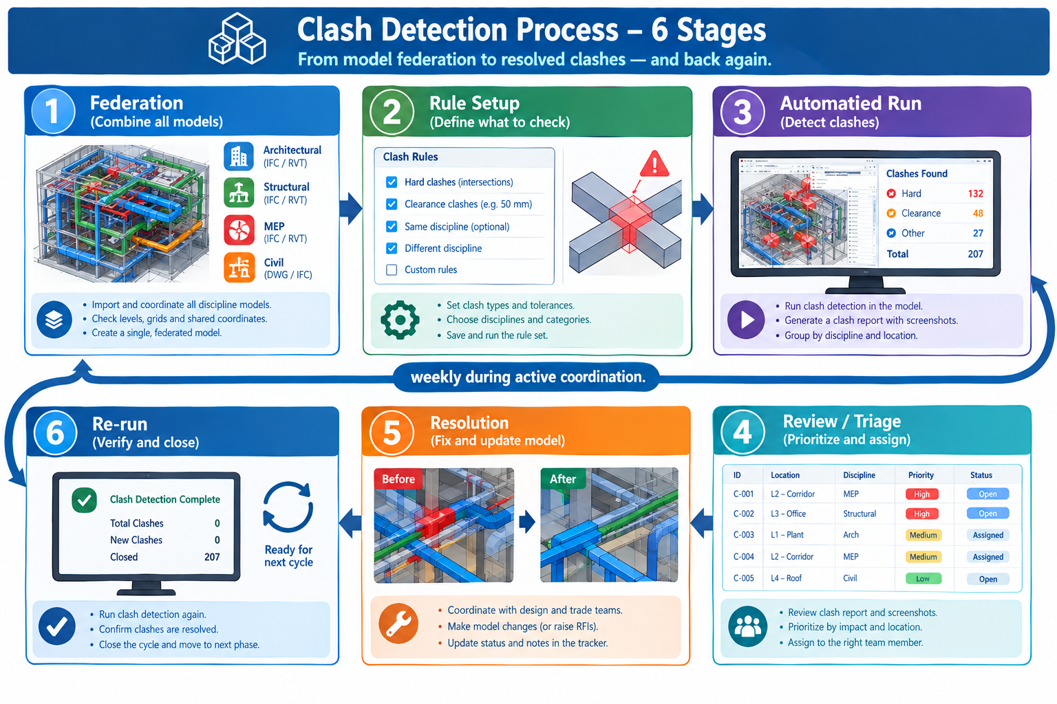
The Clash Detection Process: Six Stages From Federation to Closure
On any project of meaningful complexity, clash detection is a recurring cycle running throughout design development and continuing, at reduced frequency, through construction documentation and early construction.
| Stage | What Happens | Common Pitfall |
|---|---|---|
| 1. Model preparation and federation | Each discipline links its native model into a shared coordinate system inside a common platform | Mismatched origin points or level datums produce false clashes that waste review time |
| 2. Clash test and rule set definition | The team defines which discipline pairs are tested, what clearance buffers apply, and which categories are excluded | Testing every discipline against every other with no buffers produces thousands of low-value soft clashes that bury critical hard clashes |
| 3. Automated clash run | Software runs the defined tests and generates a report listing every detected conflict with location and severity | Running clashes only once at the end of design instead of on a recurring cycle lets conflicts accumulate undetected |
| 4. Review, triage, and assignment | The team reviews the report together, confirms real conflicts versus false positives, and assigns ownership and priority | Reviewing clashes discipline-by-discipline in isolation lets each party defer resolution without a shared decision |
| 5. Resolution and model update | The responsible discipline reroutes, resizes, or repositions the conflicting element and republishes the model | Resolving a clash locally without checking whether the fix creates a new conflict with a third, uninvolved discipline |
| 6. Re-run and closure verification | The clash test is re-run to confirm the assigned clash is actually resolved and no new clash was introduced | Marking a clash closed based on a discipline’s report alone, without re-running the automated test |
Why the Cadence of the Cycle Matters as Much as the Steps
A coordination process that runs these six stages once, at the end of design development, catches far fewer conflicts than the same process run weekly or biweekly throughout design, since every discipline is still actively changing their model, and a conflict introduced in week 10 won’t appear in a clash report generated in week 4. Mature coordination programmes typically run the full cycle weekly during the most active coordination phase, tapering to biweekly or on-demand once the clash count drops to a low, stable baseline.
The cadence also affects the coordination meeting itself. A team walking in with a clash report generated the same week discusses current, relevant conflicts. A team working from a month-old report is likely discussing conflicts one discipline has already partially resolved and others that no longer exist, wasting meeting time reconciling the report against the current model state before real coordination discussion can begin.
Clash Detection Tools: What Each One Is Actually Good At
No single tool covers every part of the process equally well. Most mature coordination programmes combine a geometric clash engine, a rule-based compliance checker, and increasingly a cloud-based issue tracker.
| Tool | Primary Use Case | Typical Users | Notes |
|---|---|---|---|
| Autodesk Navisworks | Multi-discipline federation and automated clash detection | General contractors, MEP coordinators, BIM managers | Most widely used platform in construction; strong scheduling integration, steeper learning curve for rule-based setup |
| Solibri Model Checker | Rule-based model checking with strong code and standard compliance emphasis | Architects, code reviewers, owner QA teams | Particularly strong for non-collision and rule-based clashes; often used alongside Navisworks |
| BIM Collaborate (Autodesk Construction Cloud) | Cloud-based, continuous clash detection integrated with issue tracking | Distributed project teams needing real-time coordination | Removes manual federation, but requires all disciplines to publish to a shared cloud environment |
| BIMcollab | Cross-platform issue and clash management | Multi-vendor teams using different authoring tools | Uses BCF for cross-vendor issue exchange; typically manages clashes detected by another tool rather than detecting them itself |
| Trimble Tekla BIMsight/Connect | Federation and clash review for structural and precast-heavy projects | Structural engineers, precast/steel fabricators | Strong structural and fabrication-detail handling; less common as the primary MEP platform |
| Revit built-in interference check | Early, single-discipline or lightly federated checking during design development | Design teams performing preliminary self-checks | Useful first-pass check; not a substitute for a dedicated coordination platform |
Choosing Between Desktop and Cloud-Based Coordination
The most consequential tool decision on most projects isn’t which specific software brand to use, but whether coordination runs on a desktop-federated model, where a BIM coordinator manually links each discipline’s exported file on a recurring cycle, or a cloud-based model, where each discipline publishes directly to a shared environment and clash detection runs automatically on every publish. Desktop federation gives more direct control over exactly which model versions are tested and is often preferred by small, co-located coordination teams. Cloud-based coordination reduces manual federation workload and gives near-real-time visibility, which tends to matter more with a large subcontractor pool or a geographically distributed design team.
Neither approach eliminates the need for review, triage, and resolution; a faster clash run only accelerates stage 3 of the six-stage cycle. Projects adopting cloud-based automatic clash detection without strengthening the review stage often end up with faster but not more effective coordination, more reports generated, same bottleneck at the human review stage.
Worked Examples
A commercial office tower ceiling void: A 32-storey office tower’s typical floor had a tightly constrained 600mm ceiling void carrying structural steel, HVAC ductwork, sprinkler mains, electrical bus duct, and data cable tray. Early coordination used 2D reflected ceiling plans reviewed independently by each trade, with the design team assuming the void depth was adequate based on a previous similar project.
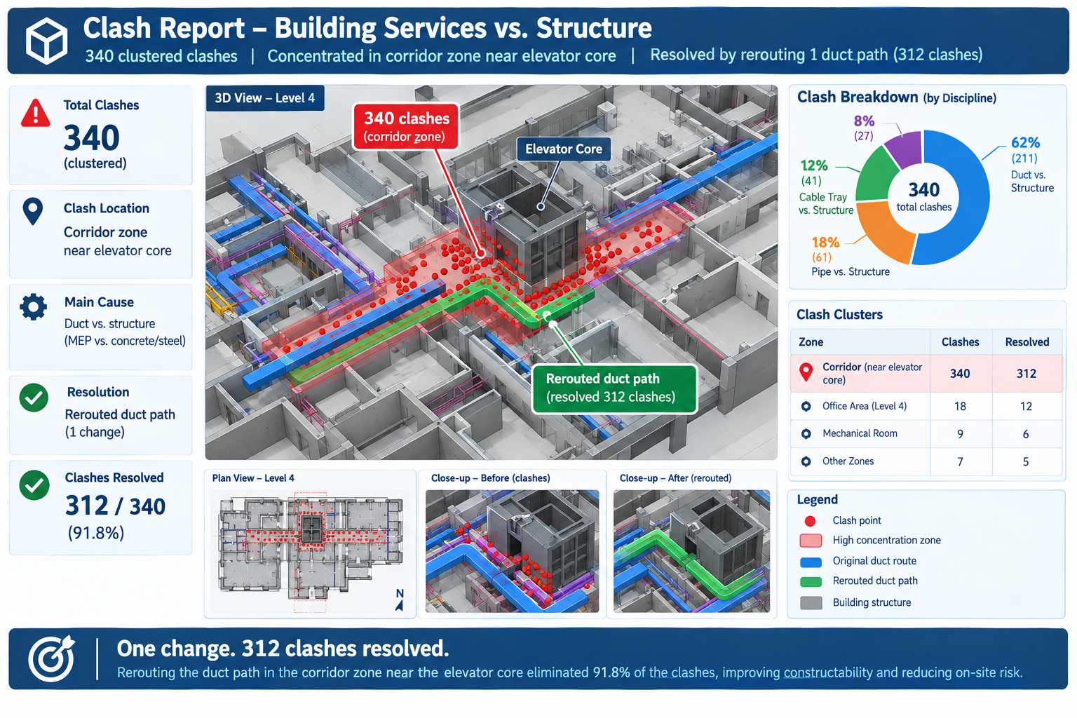
The first federated clash test, run at roughly 60% model completion for mechanical and electrical, returned 340 hard clashes concentrated in the corridor zones outside the elevator core, where the largest primary ductwork, the fire sprinkler main, and the electrical bus duct all needed to cross the same limited ceiling void width at the same points. The clustering made clear that the 600mm void depth, adequate for a typical open office bay, wasn’t adequate where all major distribution systems converged near the core.
Rather than resolving 340 individual clashes one at a time, the coordination team used the clustering to identify the root design issue and raise it as a single decision: increase the void depth in that specific zone by 150mm, or reroute the primary ductwork through the adjacent open office bays instead. The team chose the reroute, implemented as a single change to the mechanical model. This resolved 312 of the 340 clashes in one model update, with the remaining 28 resolved individually in the next cycle. Because the pattern was caught at 60% model completion, the mechanical redesign was absorbed within the existing design schedule with no impact to the construction start date.
A precast parking structure column interface: A precast concrete parking structure had its column and beam connections modelled by the precast fabricator to a high level of detail, while the cast-in-place foundation and embedded electrical conduit were modelled separately by the structural and electrical engineers, on a coordination timeline running roughly two weeks behind the fabricator’s shop drawing schedule.
A clash test between the precast column base connection detail and the electrical conduit model found 14 hard clashes where embedded conduit for card-access control at ground-floor columns passed directly through the location reserved for precast column base plates and anchor bolts, a conflict invisible in either discipline’s drawings alone since the precast connection detail existed only in the fabricator’s shop model, not in the structural design model the electrical engineer had coordinated against.
Since the precast shop drawings were already in production and changing the anchor bolt pattern would have affected a connection type used at every ground-floor column, the team resolved the conflict by rerouting the conduit instead, adding a documented offset detail at each affected column. Resolving it as a single standard detail, rather than 14 separate site improvisations, meant the electrical contractor could issue one instruction covering every affected column, and the precast erection schedule proceeded without delay.
Frequently Asked Questions
At what stage of a project should clash detection start?
As soon as at least two disciplines have models with enough real geometry to test meaningfully, typically midway through schematic design or early design development, even with models still incomplete. Starting early catches large, structural-level conflicts (like the office tower ceiling void) while they’re still cheap to fix with a major routing decision, rather than waiting until construction documentation when the conflict can only be fixed by unpicking hundreds of already-detailed elements. Early clash detection produces more false positives from incomplete modelling, a reasonable cost for catching major conflicts while inexpensive to resolve.
Who is responsible for resolving a clash once it’s detected?
The clash report identifies the elements and disciplines involved, but resolution responsibility is typically assigned during review and triage based on project-specific coordination protocols, not automatically by the software. Common conventions: whichever discipline’s element is easier or cheaper to move (a duct is usually easier to reroute than a structural beam), whichever discipline routed later in the design sequence, or whichever the project’s coordination protocol designates as having priority in a given zone. These conventions should be agreed and documented before coordination begins, since disputes over whose model should change are a common source of resolution delay.
Does clash detection replace the need for a BIM coordinator or coordination meetings?
No. Clash detection software automates the geometric testing stage, but review, triage, assignment, and verification all require human judgment the software doesn’t perform. A BIM coordinator’s role shifts with mature tools from manually cross-checking drawings to managing the clash register, facilitating coordination discussion, and ensuring resolutions are actually verified by re-running the clash test, arguably a more valuable use of that role’s time, not one clash detection eliminates.
How many clashes is normal to find on a typical project?
Raw clash count varies enormously by project complexity, model maturity, and rule configuration, so it isn’t a meaningful benchmark alone. A more useful measure is the trend over time: a healthy programme shows open clash count rising as new disciplines’ models are added early in design, then declining steadily as resolution works through the backlog, converging toward a low, stable number by the time construction documents are issued. A flat or rising clash count through construction documentation signals the resolution stage isn’t keeping pace with detection.
Can clash detection be run without a full BIM model for every discipline?
Clash detection requires three-dimensional geometry to test, so a discipline still working in 2D drawings can’t be included in automated clash tests, limiting the programme’s coverage to disciplines that have modelled their scope in 3D. Many projects run a partial clash detection programme early, testing disciplines with adequate model maturity while others catch up, expanding the test matrix as more disciplines reach the required detail level. A project relying on 2D drawings for any major building system carries the same risk that produced the hospital corridor conflict, regardless of how well the 3D-modelled disciplines are coordinated.
Key Takeaways
The hospital corridor conflict existed in the design for five months before it was found, not because anyone reviewing the drawings was careless, but because the drawing format itself, separate 2D plan views, couldn’t show a three-way conflict between a diagonal brace, a duct, and a fire main occupying the same vertical space. This is the structural limitation clash detection exists to remove: three-dimensional conflicts require a three-dimensional test to be reliably found before they reach the field.
The office tower and precast parking structure examples show what that test looks like in practice: not a single pass/fail check, but a recurring cycle that surfaces conflicts early enough to fix as design decisions rather than field improvisations, and groups related conflicts so a team resolves a systemic issue once rather than fighting the same underlying conflict dozens of times. The software finds the conflicts; the process built around it, federation, rule definition, review, assignment, resolution, and verification, following the coordination protocols outlined in the National BIM Standard-United States, is what actually prevents them from reaching the job site.
Projects that treat clash detection as a checkbox run once before construction documents are issued get a fraction of its value. Projects that run it as a disciplined, recurring cycle throughout design, with a clear resolution protocol and a verified closure step, turn what’s otherwise an invisible risk, discovered only when a foreman looks up at the wrong moment, into a managed, tracked, and resolved part of the design process.
Leave a Reply