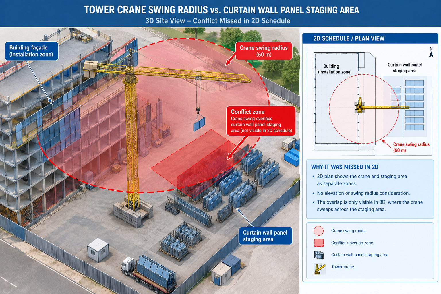
A 22-storey mixed-use tower was seven months into structural erection when the general contractor’s superintendent discovered that the tower crane’s planned swing radius for lifting curtain wall panels to the sixth floor would sweep directly through the staging area where those same panels were scheduled to be stored before installation. Two activities, each individually scheduled correctly, had never been checked against each other in three dimensions.
The schedule, built and maintained in a standalone scheduling tool with no link to the building model, showed both activities happening the same week because that week’s sequence looked correct on paper: steel substantially complete, curtain wall crew mobilised, crane available. Nobody had checked whether the crane could physically reach the panels without its swing path crossing the space where the panels themselves were sitting.
| Quick answer: The conflict cost eleven days: four to identify a temporary alternate staging location, three to renegotiate the crane’s lift sequence with the steel erector, and four of lost curtain wall progress implementing the new sequence. Every individual activity in the original schedule had been logically planned. What was missing wasn’t planning discipline; it was a way to test the plan against the physical, three-dimensional reality of the site before committing crews and equipment to it. This is what BIM does for delay prevention: it’s not one tool that fixes delays generally, but a set of distinct methods, each targeted at a specific delay mechanism, from clash detection for physical conflicts to 4D simulation for sequencing conflicts. |
This article covers the six most common causes of construction delay, the specific BIM dimensions and methods that address each one, the six-stage process for implementing BIM in a way that actually prevents delays, and two worked examples showing the argument in practice.
The Six Most Common Causes of Construction Delay, and What BIM Does About Each
Construction delays rarely have a single cause; they accumulate from recurring, well-understood problems that appear on nearly every project. What varies is how early each is caught and how disruptive the fix is once found.
| Delay Cause | Description | Typical Schedule Impact | BIM Method / Tool |
|---|---|---|---|
| Design conflicts discovered on site | 2D drawings didn’t reveal a physical overlap between systems before construction | 1-4 weeks per major conflict | 3D clash detection (Navisworks, Solibri) run on a recurring cycle through design |
| Inaccurate or incomplete quantity take-offs | Manual take-offs from 2D drawings are wrong, causing late reorders or oversupply | 1-3 weeks per major shortfall | 5D BIM quantity take-off and cost estimating tools, model-linked and auto-updating |
| Unclear or outdated construction sequence | The site team works from a static schedule that doesn’t reflect design evolution | 1-6 weeks cumulative from repeated resequencing | 4D BIM scheduling simulation, schedule linked directly to model elements |
| Late or unresolved RFIs | Design ambiguities aren’t caught until a subcontractor in the field can’t proceed | 3-15 days per RFI cycle, multiplied by stalled critical-path work | Federated model as a common reference; cloud-based CDE for RFI tracking |
| Prefabrication and offsite fabrication errors | Components fabricated from 2D shop drawings don’t fit as-built conditions | 2-8 weeks depending on re-fabrication lead time | Model-based fabrication with digital model handoff, bypassing 2D shop drawings |
| Poor stakeholder communication and approval delays | Owners, architects, and contractors interpret drawings differently | 1-4 weeks per major disagreement | Cloud-based model viewers and common data environments for real-time shared visualisation |
Why RFIs Are the Clearest Early-Warning Signal
Among these six causes, the volume and cycle time of requests for information (RFIs) deserves particular attention, since it’s the delay mechanism most directly visible in ongoing project data, long before the delay itself shows up in the schedule. An RFI is, by definition, a moment where the field can’t proceed without clarification, and every day it stays open is a day the affected activity, and often activities scheduled after it, can’t move forward with certainty. Projects that track RFI volume and cycle time as a leading indicator, rather than only reviewing schedule variance after the fact, can catch a coordination breakdown while it’s still a paperwork problem rather than a field delay.
A shared, coordinated 3D model reduces RFI volume by resolving underlying ambiguity before construction reaches that point, and reduces RFI cycle time for the RFIs that still occur by giving the responding party an exact model location and geometry to reference rather than a written description requiring back-and-forth clarification. Both effects compound: fewer RFIs, each resolved faster, is a meaningfully different schedule risk profile than a project relying on 2D drawings alone.
The BIM Dimensions That Do the Delay-Prevention Work
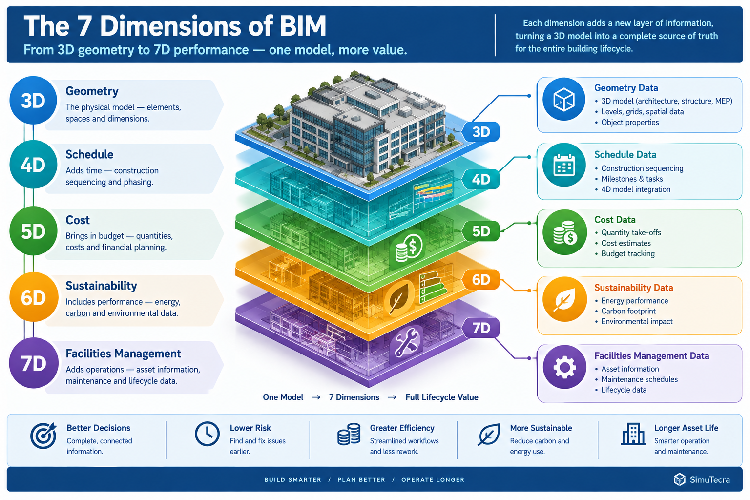
The “dimension” numbering (4D, 5D, and so on) is more convenient shorthand than a strict technical hierarchy, but each does correspond to a distinct type of data linked to the model and a distinct delay-prevention mechanism.
| BIM Dimension | What It Adds | Delay-Prevention Mechanism | Representative Tools |
|---|---|---|---|
| 3D, Geometry | Three-dimensional representation of every building element from every discipline | Makes physical conflicts visible before construction, replacing flat 2D overlay review | Revit, ArchiCAD, Tekla Structures |
| 4D, Schedule | Schedule activities linked directly to model elements | Reveals sequencing conflicts, an element scheduled before its access route or preceding trade is complete, before it reaches the field | Navisworks TimeLiner, Synchro |
| 5D, Cost | Cost data linked to model elements, auto-updating as design changes | Prevents late-discovered budget overruns from triggering mid-construction redesign scope cuts | Autodesk Assemble, CostX, Vico Office |
| 6D, Sustainability | Energy and sustainability data linked to elements | Prevents late-stage code or certification compliance failures requiring redesign after construction starts | Autodesk Insight, IES Virtual Environment |
| 7D, Facilities management | Asset and maintenance data linked to elements for post-construction use | Reduces commissioning delays from incomplete or inconsistent handover documentation | FM:Systems, Archibus, Autodesk Tandem |
4D Scheduling: The Dimension Most Directly Tied to Delay Prevention
Of these dimensions, 4D scheduling aims most directly at delay prevention, since it’s the only one that tests the time dimension of the project against the model rather than cost, sustainability, or facilities data. The tower crane conflict is a canonical 4D problem: two activities correctly scheduled in isolation created a physical conflict only visible when their spatial footprint was checked against each other during the same time window. A 4D simulation run before the schedule is finalised, and re-run as the schedule and design evolve through construction, catches exactly this category of conflict before crews, equipment, and materials commit to a sequence that can’t physically work.
The practical value of 4D simulation depends heavily on keeping it current. A 4D model built once at project kickoff provides a useful early check but a false sense of security later if not updated as both the schedule and design continue to change. Projects that treat 4D simulation as a living tool, updated on the same recurring cycle as clash detection, catch sequencing conflicts throughout construction rather than only at the outset.
Implementing BIM for Delay Prevention: A Six-Stage Process
Owning BIM software, or even having each discipline produce a 3D model, doesn’t by itself prevent delays. The delay-prevention benefit comes from a disciplined process built around the model.
| Stage | Activity | Common Pitfall |
|---|---|---|
| 1. BIM execution planning | Define BIM goals, level of development requirements, model ownership, and specific delay-prevention uses before design begins | Treating the BEP as a compliance formality that’s signed but not actually followed |
| 2. Model authoring and federation | Each discipline authors to the agreed detail level and federates into a shared environment on a recurring cycle | Inconsistent levels of detail across disciplines, hiding conflicts because one discipline hasn’t modelled that scope yet |
| 3. 4D schedule linking | Schedule activities are linked to model elements and simulated to check access, logistics, and sequencing before the schedule is finalised | Building the simulation once at kickoff and never updating it as schedule and design evolve |
| 4. Ongoing coordination and clash resolution | Clash detection continues on a recurring cycle through design and into early construction | Coordination slowing or stopping once construction starts, even though field conditions keep generating new conflicts |
| 5. Fabrication and construction model handoff | Model geometry hands off directly to fabricators rather than being redrawn into 2D shop drawings | Fabricators working from an outdated model version due to unclear version control |
| 6. Facilities handover and closeout | The as-built model, updated with field-verified changes, is delivered to the owner with asset and maintenance data | Deferring model updates until the end, producing a rushed, incomplete as-built model |
The BIM Execution Plan: Where Delay Prevention Is Won or Lost
The first stage is disproportionately important because it defines whether the remaining five are actually structured to prevent delays or are simply producing a coordinated model as a documentation exercise. A BIM execution plan (BEP) that specifies model federation and clash detection but not 4D schedule linking will catch physical conflicts but miss sequencing conflicts of exactly the kind that delayed the tower crane example.
A BEP that doesn’t specify how the as-built model will be maintained through construction will produce a coordinated design model but a facilities handover gap at project close. Each specific delay-prevention use, clash detection, 4D sequencing, quantity take-off, fabrication handoff, facilities data, should be explicitly scoped in the BEP, since a model built without a defined use for a specific benefit rarely delivers that benefit by accident.
Measured Benefits: Where BIM’s Delay Reduction Shows Up in Project Data
Rather than treating “BIM reduces delays” as a single unmeasurable claim, each benefit ties to a specific project metric a scheduler or owner would already be tracking.
| Benefit | Mechanism | Where It Shows Up | Caveats |
|---|---|---|---|
| Fewer schedule-impacting RFIs | Geometric ambiguities resolved in the coordinated model before construction | RFI logs and critical-path variance reports | Largest for MEP-heavy, congested-space projects; smaller relative benefit for simpler projects |
| Reduced rework and change orders | Conflicts caught in the model fixed as design changes rather than field improvisations | Change order logs and field rework tracking | Savings depend on how disciplined the resolution and verification process actually is |
| Faster procurement and fabrication cycles | Accurate, model-derived quantities shorten time from design finalisation to delivery | Procurement lead-time tracking and fabrication schedule adherence | Depends on trade contractors’ own fabrication capability and willingness to work from model data |
| More reliable schedule commitments | 4D simulation identifies conflicts before the schedule is issued | Schedule variance reports and revision frequency during construction | Simulation quality depends on how current the underlying model and schedule data are |
| Shorter commissioning and closeout | Accurate, continuously updated as-built model reduces documentation gaps | Commissioning schedule adherence, substantial-to-final completion gap | Requires the owner’s facilities team to have systems in place to actually use the handover data |
Why the Benefit Is Concentrated in Complex, Multi-Trade Projects
The delay-reduction benefit isn’t uniform across project types; it scales with the density of interdependent systems and trades, since that density determines how many opportunities exist for the kind of conflict BIM catches. A single-storey warehouse with a simple structural system and minimal MEP scope has relatively few opportunities for a tower-crane-style sequencing conflict or ceiling-void congestion, so the absolute delay-prevention benefit of a full BIM programme is smaller, even though the underlying methods still apply.
A hospital, laboratory, or high-rise mixed-use tower, with dense, interdependent MEP systems, tight sequencing, and multiple concurrent trades in the same physical space, is where the benefit concentrates most heavily, since those are exactly the conditions under which 2D-only coordination is least reliable.
Worked Examples
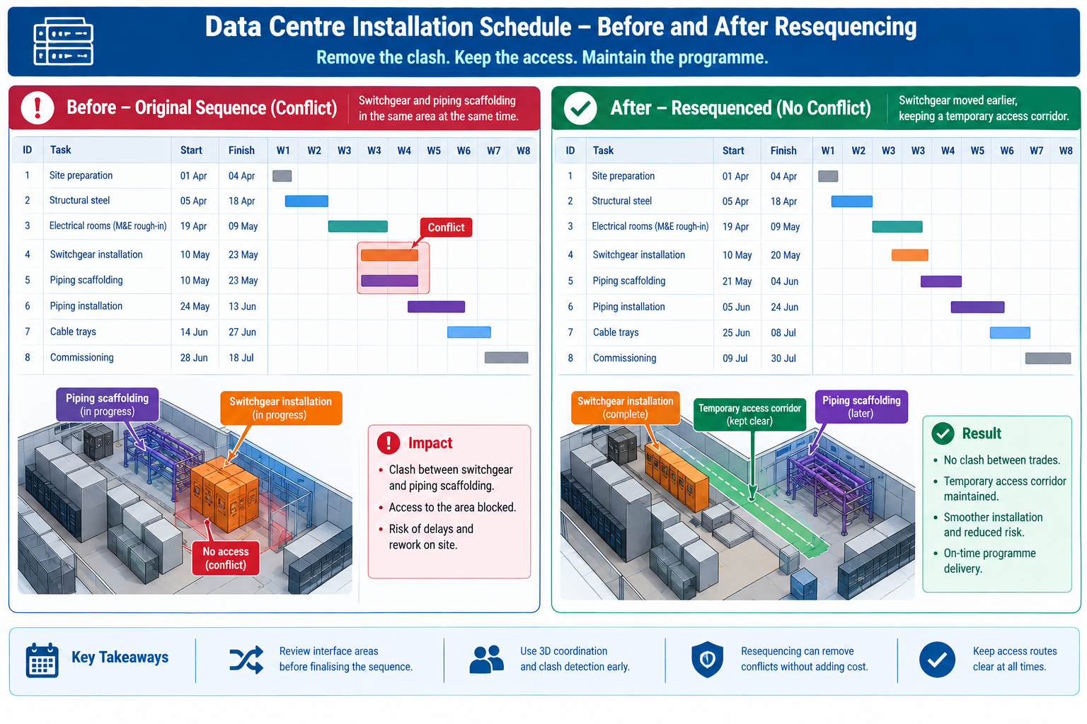
A data centre fit-out schedule: A hyperscale data centre fit-out had an aggressive 34-week schedule driven by a fixed equipment delivery date, with cooling infrastructure, electrical switchgear, and server rack installation sequenced to overlap heavily in the same rooms. The original schedule, built in a standalone tool by an experienced scheduler, showed a logically sound sequence with appropriate lead and lag times.
When linked to the coordinated model and simulated in 4D, the simulation revealed that the electrical switchgear installation crew, scheduled for weeks 18 through 21, would need access to a room that the cooling infrastructure crew’s overhead chilled-water piping, scheduled for week 17, would already have enclosed with scaffolding and temporary bracing blocking the switchgear’s only practical delivery path.
The simulation gave the team six weeks of advance warning, time to resequence the chilled-water piping installation to leave a temporary access corridor open until the switchgear was delivered and positioned, then complete the remaining piping afterward, a one-day schedule logic change made in the office. This avoided what the team estimated would otherwise have been a two-to-three week delay bringing in additional rigging equipment to manoeuvre the switchgear around completed piping and scaffolding, a delay that would have directly threatened the fixed equipment delivery date the entire schedule was built around.
A renovation project with unknown existing conditions: A hospital renovation involved gutting and rebuilding three floors of an operating 1980s-era building while adjacent floors stayed occupied and in clinical use. The original design was based on the building’s archived 2D drawings, known to be incomplete and, in places, inconsistent with the building’s actual as-built condition after four decades of undocumented modifications.
The project team commissioned a 3D laser scan of existing conditions before finalising the renovation design, converting the point-cloud data into an as-built 3D model capturing the building’s true existing structure, ductwork, and piping routes, rather than relying on archived drawings. The new design was then coordinated directly against this verified as-built model.
Scan-based coordination identified 47 locations where the building’s actual condition differed materially from the archived drawings, including a structural beam relocated during a 1990s renovation, reflected in no drawing set, that would have directly conflicted with a new mechanical shaft location in the original design.
Because these discrepancies were identified against a verified model before construction began, the design was adjusted in the office rather than discovered by a demolition crew mid-renovation, in an occupied hospital where an unplanned structural or MEP discovery carries especially high schedule and safety risk. The team credited the upfront scanning investment with avoiding an estimated several weeks of cumulative delay that unknown existing-condition conflicts would otherwise have caused across the renovation’s three floors.
Frequently Asked Questions
Does BIM eliminate construction delays entirely?
No single method eliminates delays entirely, since some causes, weather, material supply chain disruption, labour availability, sit outside what a coordinated model and schedule simulation can address. BIM’s delay-prevention benefit concentrates specifically in the categories covered here: design conflicts, sequencing conflicts, quantity and procurement errors, RFI cycle time, fabrication errors, and stakeholder miscommunication. Projects with a mature BIM programme still experience delays from external causes; the argument for BIM is that it removes a specific, large, and largely preventable category of delay, not that it removes delay risk altogether.
How early in a project should 4D scheduling begin?
As soon as the design model and construction schedule both have enough detail to link meaningfully, typically once design has progressed into construction documentation and the contractor’s detailed schedule is being developed, though a preliminary 4D simulation using design-development-level detail can still catch major sequencing and logistics conflicts earlier. Both examples in this article depended on the simulation being run and reviewed well before the affected activities were due to start; a simulation reviewed only in the same week as the activity it covers provides little of the warning time that makes the method valuable.
Is BIM-driven delay prevention only relevant to large, complex projects?
The underlying methods apply at any scale, but the benefit’s magnitude scales with project complexity. A small, simple project with few interdependent systems will still benefit from basic 3D coordination and clash checking, but is less likely to justify the full cost of a 5D cost-linked or 7D facilities-management programme. Scope the BIM execution plan to the specific delay risks the project actually carries, rather than applying every available BIM dimension uniformly regardless of size.
Who is responsible for maintaining the 4D and coordination models through construction?
This should be explicitly assigned during BIM execution planning, typically to a BIM coordinator role that may sit within the general contractor’s project team, a dedicated BIM management subcontractor, or occasionally the design team depending on delivery method. The key requirement, regardless of who holds the role, is that the same party or a clearly defined handoff maintains both the coordination model and its link to the live construction schedule throughout the project, since a simulation or clash register that falls out of sync with the current design and schedule loses much of its delay-prevention value.
What is the most common reason a BIM programme fails to actually reduce delays?
Treating model creation as the deliverable rather than the coordination and scheduling process built around the model. The model finds conflicts, but a defined process for reviewing, prioritising, resolving, and verifying those conflicts, and for keeping the schedule link current, is what actually converts that information into prevented delays. A beautifully modelled building with no defined clash resolution protocol, no 4D update cadence, and no clear model ownership through construction will still experience most of the delay causes in this article’s opening table, because the model alone resolves nothing; the process around it does.
Key Takeaways
The tower crane conflict cost eleven days on a schedule where every individual activity had been planned correctly. The data centre and hospital renovation examples show what changes when the schedule and design are tested against each other, and against verified existing conditions, before crews and equipment commit to a sequence. In every case, the underlying problem was the same: a plan internally consistent on paper but never checked against the physical, three-dimensional, time-based reality of the actual site.
BIM reduces construction delays specifically because it makes that check possible before commitment rather than after, whether the conflict is geometric (caught by clash detection), sequential (caught by 4D simulation), or based on existing conditions the original drawings never accurately captured (caught by as-built scanning and model verification). None of these methods work by accident; each requires the deliberate process described in the six implementation stages, from execution planning through facilities handover, following the coordination framework in the National BIM Standard-United States, to actually convert model and schedule data into prevented delays rather than an expensive but unused coordination exercise.
Projects that build this process in from the start, and maintain it through the full construction period rather than treating coordination as a design-phase-only activity, consistently show fewer schedule-impacting RFIs, less rework, more reliable schedule commitments, and shorter closeout periods than projects relying on 2D coordination and standalone scheduling tools. The eleven days lost to the tower crane conflict, and the weeks avoided in the data centre and hospital examples, are the same underlying quantity viewed from opposite sides: the cost of not testing the plan against reality, and the value of testing it in time to still change course.

Leave a Reply