
A structural engineer’s design drawings tell you what to build. A steel detailer’s shop drawings tell you exactly how to build it. Without that second set of documents, fabricators are left guessing, and guessing in structural steel is a problem that shows up on-site as misaligned connections, wrong-length members, and weeks of expensive rework.
Structural steel detailing is the discipline that bridges the gap between engineering design and fabrication. It takes the structural engineer’s intent, member sizes, load paths, connection zones, and translates it into manufacturing-ready drawings that a steel fabricator can actually work from. This guide explains what steel detailing is, what a complete shop drawing package includes, how the process works, and what happens when any part of it is done poorly.
What Is Structural Steel Detailing?
Structural steel detailing is the process of producing detailed technical drawings for every component of a steel-framed structure, every column, beam, brace, connection plate, and anchor bolt, with enough precision that a fabricator can manufacture each piece in a workshop without ever visiting the construction site.
The structural engineer defines the design: which member sizes carry which loads, where the columns go, what the connection zones look like. The steel detailer translates that design into fabrication instructions: exact cut lengths, hole patterns, weld specifications, bolt grades, member mark numbers, and surface treatment requirements. These are two fundamentally different documents serving two different audiences.
| Structural engineers define the ‘what’ and ‘why’ of a steel structure. Steel detailers define the ‘how’, in enough detail that fabrication can begin without further interpretation. |
In practice, structural engineers do not typically produce shop drawings, and fabricators cannot manufacture complex steelwork from structural design drawings alone. The detailer occupies the critical middle ground, and their work directly determines whether steel arrives on site fitting correctly or requiring costly modification.
Who Uses Steel Shop Drawings?
- Steel fabricators: Use shop drawings as the primary manufacturing document. Every cut, drill, bend, and weld is made to the shop drawing specification.
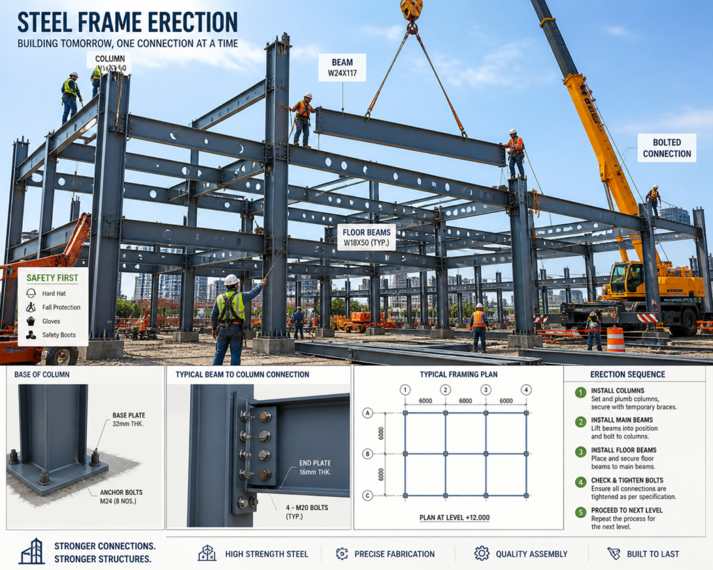
- Site erectors: Use erection drawings (a subset of the shop drawing package) to locate, orient, and assemble steel members in the correct sequence.
- Structural engineers: Review and approve shop drawings before fabrication begins, confirming they accurately represent the design intent.
- Contractors and project managers: Use the drawing package for programme planning, procurement, and site coordination with other trades.
- Inspectors and certifiers: Reference shop drawings during quality assurance inspections to verify that fabricated members match the approved specification.
What a Complete Steel Shop Drawing Package Includes
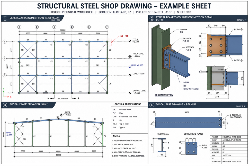
A shop drawing package is not a single sheet, it is a coordinated set of documents covering every aspect of the steel structure from overall layout down to individual component fabrication. Here are the five core drawing types that make up a complete package:
| Drawing Type | What It Shows | Who Uses It |
|---|---|---|
| General Arrangement (GA) Drawing | The overall steel framework, column grid, beam layout, levels, key dimensions, and member mark references. The big-picture roadmap of the structure. | All stakeholders: engineers, fabricators, erectors, contractors. Always the first document reviewed. |
| Fabrication Shop Drawing | Individual member details, exact lengths, cross-section sizes, hole locations, end cuts, weld preparation, surface treatment, and member mark numbers. | Steel fabricator in the workshop. This is the primary manufacturing document. |
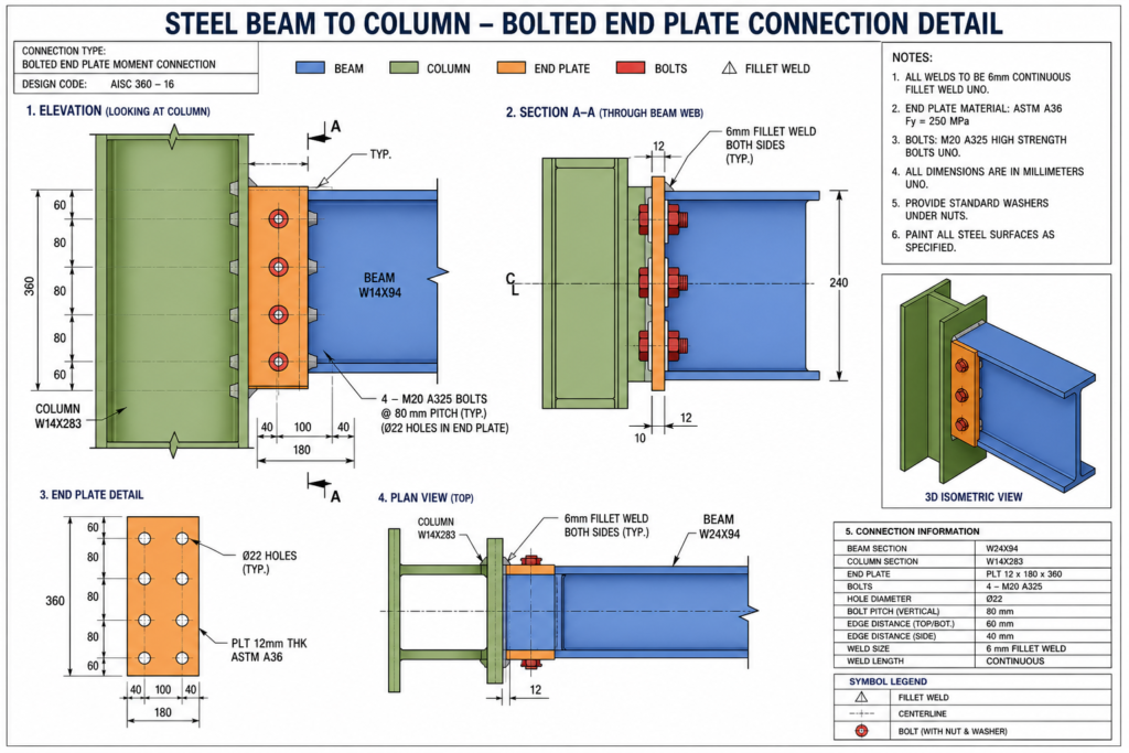
| Connection Detail Drawing | How members are joined, end plate dimensions, bolt specifications (grade, size, spacing), weld types (fillet, groove), stiffener plates, cleats, and gussets. | Fabricator and structural engineer. Connection details are the most safety-critical drawings in the package. |
| Erection Drawing | Site assembly instructions, member marks matched to positions on the structure, erection sequence, temporary bracing requirements, and orientation notes. | Site erectors and crane operators. Governs how and in what order steel goes up. |
| Anchor Bolt / Baseplate Drawing | The interface between the steel structure and its foundations, anchor bolt patterns, projection heights, baseplate dimensions, grout details. | Civil/structural engineer and site team. Must be issued before concrete is poured. |
What a Fabrication Shop Drawing Contains in Detail
The fabrication drawing is the most detail-intensive document in the package. For every individual steel member, whether it is a 200 mm universal column or a 12 m long crane beam, the fabrication drawing includes:
- Member mark number (a unique identifier used to track the piece from workshop to site)
- Cross-section size and steel grade (e.g. 310UC97 Grade 350, or W12x96 A992)
- Overall length and end-to-end dimensions
- Hole pattern: diameter, spacing, edge distance, and bolt gauge lines for every connection
- End preparation: square cut, coped, notched, or shaped to suit the connection
- Weld callouts: weld type, size, length, and location using standard weld symbols
- Stiffener plates, web plates, flange plates, and any additional fabricated elements
- Surface finish: bare steel, primed, hot-dip galvanised, or intumescent coated
- Weight of the finished member (for crane planning and logistics)
| Common problem: Connection details are the most frequently incomplete element of a structural engineer’s drawing package. When connection geometry is not specified by the engineer, the steel detailer is responsible for designing and calculating the connections, adding scope, time, and coordination requirements to the detailing process. Clarify this responsibility before starting any steel detailing engagement. |
The Steel Detailing Process: From Design Intent to Fabrication-Ready Drawings
Steel detailing follows a structured sequence. Compressing or skipping any stage increases the risk of errors that compound through fabrication and into site installation. Here is how a properly managed steel detailing process works:
Stage 1: Design Review and Input Gathering
The detailer starts by reviewing the structural engineer’s drawings in full, checking member sizes, connection zones, load transfer paths, and any special requirements. Before any drawing is started, every piece of missing information is identified and resolved. Structural drawings that leave connection design to the detailer require additional coordination before work can begin.
| Best practice: Issue a formal Request for Information (RFI) log at the start of every steel detailing project. Capturing all ambiguities before detailing starts prevents revision cycles later, each revision to a fabrication drawing after approval costs far more than the time spent resolving the RFI upfront. |
Stage 2: 3D Modelling
Most professional steel detailing today begins with a 3D model built in Tekla Structures, Advance Steel (AutoCAD), or Revit. The structural framework is modelled in full, every column, beam, brace, connection plate, and bolt, before any 2D drawings are produced. The 3D model serves as the single source of truth for all geometry.
The 3D modelling stage is where clash detection happens: two members occupying the same space, a beam centreline that misses the column by 20 mm, a stiffener plate that conflicts with a bolt head. Catching these in the model costs minutes. Catching them during fabrication costs days.
Stage 3: Drawing Generation and Annotation
With the 3D model complete and clash-free, 2D fabrication drawings are generated directly from the model geometry. Each drawing is then annotated with member marks, dimensions, hole callouts, weld symbols, material grades, surface treatment, and any special notes. The drawings are checked against the structural engineer’s specifications and reviewed internally before submission.
Stage 4: Engineer Review and Approval
The complete drawing package is submitted to the structural engineer of record for review. The engineer checks that every drawing accurately reflects the design intent, member sizes, connection types, load paths, and any project-specific requirements. Comments are returned, revisions are made, and the cycle continues until the drawings receive an approved-for-fabrication stamp.
| Drawings issued for fabrication without engineer approval are a liability risk for every party in the supply chain. Approved-for-fabrication status is a non-negotiable gate before any steel is cut. |
Stage 5: Issue and Fabrication
Approved drawings are issued to the fabricator, along with any associated NC (numerical control) data files for automated cutting and drilling equipment. The fabricator manufactures each member to the drawing specification, marks it with its member number, and stages it for delivery to site in erection sequence.
What Happens When Steel Detailing Is Done Poorly
The consequences of poor steel detailing are not abstract, they appear as concrete, measurable problems on the fabrication floor and construction site. Here are the most common failure modes and what they cost:
| Problem | How It Manifests on Site | Typical Cost Impact |
|---|---|---|
| Incorrect hole patterns | Bolts do not align when members are brought together on site. Holes must be reamed, slotted, or in severe cases the member returned for refabrication. | High. Reaming is labour-intensive; refabrication requires remobilising the fabricator and delays the erection programme. |
| Wrong member lengths | Beams arrive too long or too short for their connections. Short members may require extension plates; long members cannot be forced into position. | High. Extension plating requires engineer approval and adds welding work on site, where quality control is harder than in the workshop. |
| Missing connection details | Fabricator encounters a connection type not shown on the drawings and makes an assumption. The assumption is wrong. Connection is built incorrectly. | Very high. Structural integrity is compromised. Engineer review, remediation work, and potential programme shutdown may follow. |
| Outdated revision used for fabrication | Steel is manufactured to a superseded revision of the drawing. Members arrive on site that do not match the current design intent. | High to very high depending on scope. Worst case is a full batch of steel scrapped and refabricated. |
| Clashes not resolved before fabrication | Two members designed to share the same space conflict during erection. Field modifications are made on site without engineering review. | Medium to high. Field modifications are expensive, slow, and often structurally suboptimal. Liability exposure increases significantly. |
Standards That Govern Structural Steel Detailing
Steel detailing does not operate in a standards vacuum. The drawings must comply with the applicable structural design code and the industry standards governing fabrication quality and drawing presentation. The most commonly referenced are:
- AISC (American Institute of Steel Construction): Governs structural steel design and fabrication in the United States. The AISC Code of Standard Practice defines the division of responsibility between engineers, detailers, and fabricators, including who is responsible for connection design when not specified by the engineer.
- AWS D1.1 (American Welding Society): The structural welding code referenced on US shop drawings for all weld specifications. Weld symbols, procedures, and inspection requirements are governed by this standard.
- ASTM material standards: Define the steel grade (e.g. ASTM A992 for wide flange sections, ASTM A36 for plates). Material callouts on shop drawings reference these standards directly.
- Eurocode 3 / BS EN 1993: The structural steel design standard used across Europe and increasingly in international projects. Detailing conventions differ from AISC in member designation, weld symbols, and bolt standards.
For international projects: Always confirm which standard set applies before beginning detailing. A drawing package produced to AISC standards and submitted to a European fabricator may use member designation systems, weld symbols, and bolt standards that the fabricator interprets differently. Agreeing the applicable standards at the start of the project is a 30-minute conversation that prevents a multi-week misunderstanding.
Frequently Asked Questions
What is the difference between structural engineer’s drawings and shop drawings?
Structural engineer’s drawings define the design, member sizes, load paths, connection zones, and overall layout. They communicate design intent but typically do not contain enough fabrication detail to manufacture from directly. Shop drawings, produced by the steel detailer, translate that design into exact manufacturing instructions: cut lengths, hole patterns, weld callouts, and surface treatments. Both sets of drawings are required on any significant steel project.
What software is used for structural steel detailing?
Tekla Structures (by Trimble) is the most widely used dedicated steel detailing platform, particularly for complex projects. Advance Steel (Autodesk, built on AutoCAD) is common in North America and Australia. Revit with structural extensions is used where BIM coordination is the primary requirement. Traditional 2D detailing is still done in AutoCAD for simpler projects or where the client requires 2D-only deliverables.
Who is responsible for connection design, the engineer or the detailer?
This depends on what the structural engineer’s drawings specify. Where connection geometry is fully specified by the engineer, the detailer documents it. Where connections are left unspecified or noted as ‘connection by detailer’, the steel detailer is responsible for designing and calculating the connection, a responsibility that requires structural knowledge, not just drafting skill. The AISC Code of Standard Practice governs this split of responsibility in the US.
How long does a steel detailing package take to produce?
It depends entirely on the scope and complexity of the structure. A simple single-storey industrial shed might be detailed in one to two weeks. A multi-storey commercial building with complex connections and BIM coordination requirements could take two to four months. The critical path items are always the completeness of the input drawings, the speed of engineer review and approval, and the management of RFIs. Incomplete inputs are the most common cause of detailing delays.
What file formats are delivered as part of a steel detailing package?
Typically: PDF (for drawing review and site use), DWG or DXF (for 2D CAD files), and IFC or native Tekla/Revit files (for 3D BIM model delivery). NC files (CNC cutting and drilling data) are often included for modern fabrication facilities with automated equipment. The required formats should be agreed with the fabricator and engineer before detailing begins.
The Bottom Line
Structural steel detailing is not a back-office function, it is the document control system that determines whether a steel structure gets built correctly, on time, and without costly surprises. Every bolt, weld, and cut on the fabrication floor is made to a shop drawing. When those drawings are complete, coordinated, and approved, fabrication runs smoothly and steel arrives on site fitting where it should.
When they are incomplete, ambiguous, or produced from inadequate inputs, the problems that follow, misaligned connections, wrong-length members, clashing geometry, rejected inspections, are expensive, time-consuming, and entirely avoidable with a properly managed detailing process.
Whether you are a fabricator needing a complete shop drawing package, a contractor managing a steel structure project, or an engineer looking for a detailing partner who will coordinate closely through the approval cycle, that is the work SimuTecra’s structural team does.
You can download the full Steel building DWG file here
| Need Steel Detailing Drawings Done Right? SimuTecra produces complete structural steel detailing packages, GA drawings, fabrication shop drawings, connection details, and erection drawings, for fabricators, contractors, and engineering firms. Delivered to AISC, AWS, or client-specified standards. Send us your structural drawings and we will come back with a clear scope, timeline, and quote. |
Leave a Reply