Design for Manufacturability (DFM) is the engineering discipline that ensures a product design can be manufactured correctly, consistently, and economically using the intended manufacturing process. It is one of the oldest principles in engineering, Frederick Taylor was writing about it in the 1880s, and Boothroyd and Dewhurst formalised the methodology in the 1970s. Yet despite over a century of formalisation, DFM violations remain one of the most common and expensive sources of production problems in manufacturing companies today.
The persistence of DFM violations in production is not a knowledge problem, most mechanical engineers understand the principles of draft angles, wall thickness uniformity, and internal corner radii. It is a systematic application problem: the DFM rules are not checked on every feature of every part, on every revision of every drawing, before every manufacturing commitment. They are checked inconsistently, incompletely, and usually only at formal design review gates that occur too late in the design process to avoid significant rework cost.
AI is changing this structural problem fundamentally. AI DFM tools apply manufacturing process rules to every geometric feature of every part, automatically, exhaustively, and in minutes rather than hours. They catch violations on hidden faces and internal features that manual review misses. They provide feedback during the design process rather than only at release gates. And they are available at the point of quoting from online manufacturing services, making DFM feedback accessible to engineers who do not have access to specialist DFM software.
This guide covers how AI improves DFM for every major manufacturing process, the specific tools that deliver this improvement, the LLM-based DFM workflows that provide value even without specialist software, and the shift from gate-based to continuous DFM that AI makes possible.
| What DFM is (and is not): DFM is the practice of designing parts and products so they can be manufactured correctly, consistently, and economically using the intended manufacturing process. It is distinct from Design for Assembly (DFA), which addresses how parts go together, and Design to Cost (DTC), which addresses cost targets. DFM is process-specific: the DFM rules for injection moulding are different from those for CNC machining, which are different from sheet metal fabrication, which are different from additive manufacturing. A design that is excellent DFM for one process may be very poor DFM for another. The first step in AI-assisted DFM is always specifying the manufacturing process, without that context, no DFM tool or LLM can provide meaningful guidance. |
Why DFM Fails Without AI: The Systematic Application Problem
The core problem with traditional DFM is not that engineers do not know the rules. It is that the rules are not applied systematically to every feature of every part, and the person applying them manually cannot cover the same ground as an automated tool that checks every face, every wall section, and every radius without sampling.
| Traditional DFM Failure Mode | Why It Happens | AI Solution |
| DFM review only at formal gates (CDR, design freeze) | Manual DFM review is time-consuming and expensive; it is performed as a stage gate rather than continuously during design | AI DFM tools run in minutes; they can be run every time a significant change is made, not just at formal gates |
| Reviewer checks visible features only | Human reviewers check the obvious faces (front, top, visible side). Interior pocket walls, back faces, and features on hidden surfaces are frequently missed | AI DFM tools check every face regardless of orientation or visibility, a draft angle violation on the bottom of an internal pocket is as likely to be caught as one on the front face |
| DFM expertise is concentrated in senior engineers | DFM knowledge is empirical, it comes from experience with tooling failures and manufacturing problems. Junior engineers lack this experience and miss violations that experienced engineers would catch | AI DFM tools encode the DFM knowledge of experienced toolmakers and process engineers into quantitative rules accessible to any engineer |
| DFM rules are not quantified, they are qualitative | Manual DFM review produces comments like ‘may need more draft’ rather than ‘this face has 0.3 degrees draft, minimum required is 1.0 degree per PTFE mould release; add 0.7 degrees minimum.’ The qualitative comment requires the designer’s interpretation; the quantified report requires a specific correction | AI DFM tools measure every feature and report the current value vs the required value with the specific correction needed |
| Different reviewers apply different standards | DFM review quality varies by reviewer, different engineers apply different minimum draft angles, different wall thickness thresholds, different aspect ratio limits based on their individual experience | AI DFM tools apply the same rule set with the same thresholds every time, independent of which engineer runs the analysis |
| DFM and design are treated as sequential activities | DFM review happens after design is complete, when the designer is psychologically committed to the design and changes feel like failure rather than improvement | Continuous AI DFM during design treats manufacturability as a design parameter alongside geometry, the designer sees DFM feedback as they work, and corrections are made at minimal cost |
How AI DFM Works: Rule-Based vs LLM-Based Approaches
AI DFM operates through two distinct mechanisms that are complementary rather than competing:
Rule-Based AI DFM: Parametric Geometry Analysis
Rule-based AI DFM tools (DFMPro, Moldex3D DFM Advisor, Xometry instant DFM) apply a library of quantified manufacturing process rules to the CAD geometry. For each rule, the tool: measures the relevant geometric parameter on every applicable feature; compares the measured value against the rule threshold; classifies the result as compliant, marginal, or non-compliant; and generates a violation report with the specific feature location, the measured value, the required value, and the recommended correction.
These tools are fast (2-20 minutes for a complete part analysis), exhaustive (every feature is checked), and consistent (the same rule is applied the same way every time). Their limitation is that they check geometry against defined rules, they cannot reason about the manufacturing context, the assembly implications, or the cost trade-offs that require engineering judgement.
LLM-Based DFM: Engineering Reasoning from Descriptions
LLM-based DFM (using Claude, ChatGPT, or other capable LLMs) approaches DFM differently. Instead of measuring CAD geometry directly, the LLM reasons about manufacturability from a description of the part geometry, the manufacturing process, the material, and the production volume. The LLM applies manufacturing process knowledge from its training data to identify likely violations, explain the manufacturing consequences, and suggest corrections.
LLM-based DFM is more flexible than rule-based tools, it can reason about unusual geometries, production context, cost implications, and process trade-offs that rule-based tools cannot address. It is less precise on dimensional checking (it cannot measure the actual draft angle on a specific face) but more capable on reasoning about design intent and manufacturing strategy. The two approaches are most powerful in combination: rule-based tools for exhaustive geometric checking; LLMs for process strategy, cost reasoning, and unusual geometry assessment.
| Dimension | Rule-Based AI DFM Tools | LLM-Based DFM | Best Combined Use |
| How it works | Parametric geometry measurement vs quantified rules | Natural language reasoning from geometry description + manufacturing knowledge | Rule-based for geometric measurement; LLM for context, strategy, and cost reasoning |
| Speed | 2-20 minutes per part | 5-15 minutes per prompt | Run rule-based first; use LLM for follow-up on flagged issues and unmeasured aspects |
| Coverage | Every feature of the CAD model, measured quantitatively | Features described in the prompt; may miss undescribed features | Rule-based ensures nothing is missed geometrically; LLM covers strategic DFM considerations |
| Requires specialist software? | Yes, DFMPro, Moldex3D, or similar ($5,000-$30,000/year) | No, free or subscription LLM account | Use specialist software where available; use LLM as accessible first-pass or supplement |
| Handles unusual geometries? | Limited, rules may not cover novel geometries | High, LLM reasons from first principles for unusual cases | LLM adds most value for unusual geometries outside specialist tool rule libraries |
| Cost reasoning? | No, geometry only | Yes, can reason about cost drivers, production volume, and process trade-offs | LLM provides cost context that rule-based tools cannot |
AI DFM for Injection Moulding
Injection moulding is the manufacturing process with the most complex and consequential DFM requirements, and the process where AI DFM tools have reached the highest maturity. Injection mould tools represent the largest upfront tooling investment in most consumer and industrial product development programmes, and modifications to an existing tool are expensive, slow, and sometimes impossible without a complete tool remake. AI DFM for injection moulding is the highest-ROI DFM AI application in product engineering.
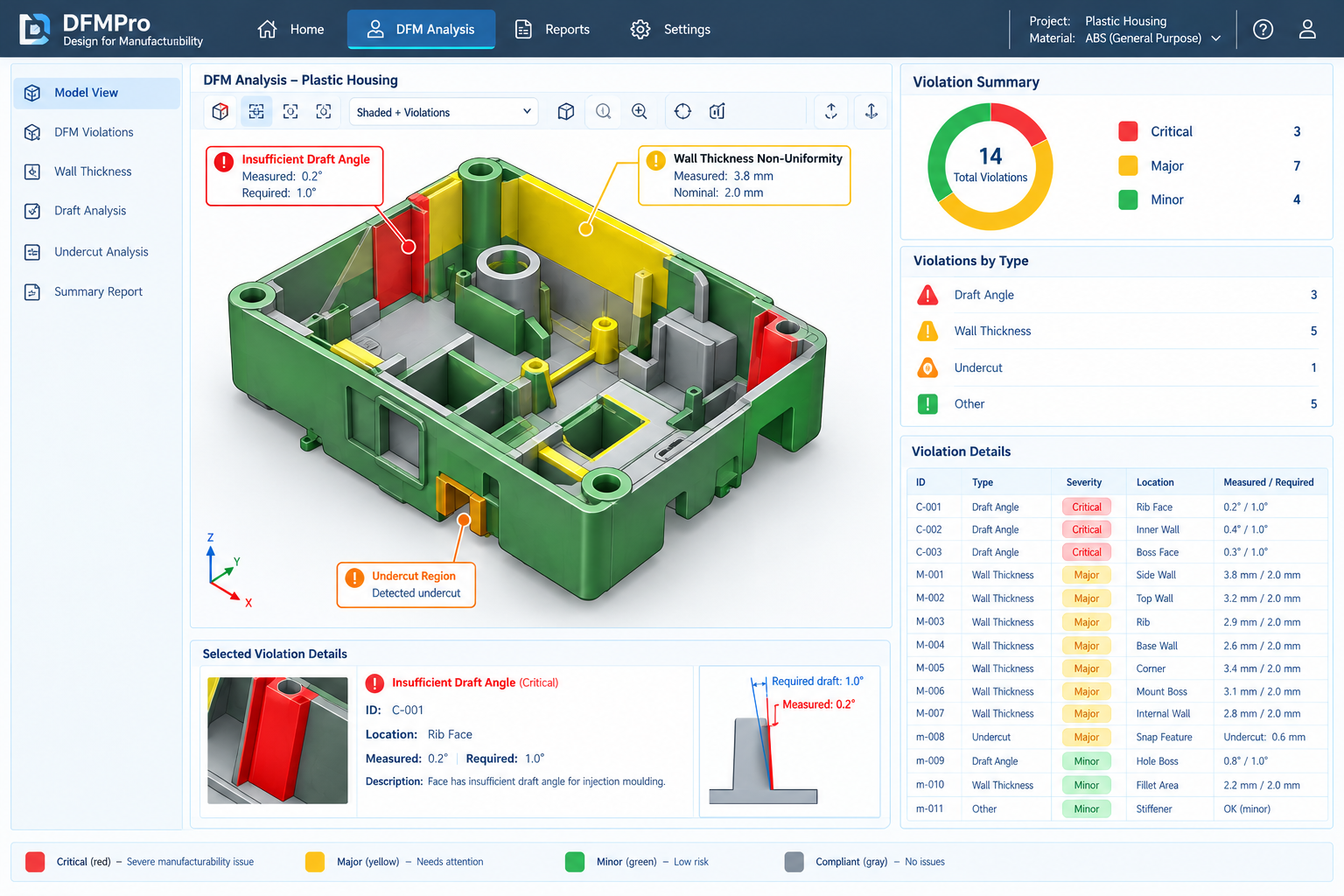
The Critical DFM Rules AI Checks for Injection Moulding
| DFM Rule | What AI Measures | Rule Threshold | Consequence of Violation | AI Tool |
| Draft angles | Angle of every face relative to the specified pull direction (mould opening direction) | Minimum 0.5 degrees for glossy surfaces; 1.0-1.5 degrees for textured surfaces; 2-3 degrees for deep draws in engineering polymers | Part sticks in mould cavity or core; drag marks on surface; tool damage; production halt | DFMPro, Moldex3D, Protolabs instant DFM |
| Wall thickness uniformity | Wall thickness at every cross-section; minimum and maximum and ratio of max to min | Maximum variation: 25% of nominal wall thickness (e.g. nominal 2mm: max allowable 2.5mm, min 1.5mm); sharp transitions flagged | Thick sections sink (cosmetic defects); thin sections fill poorly; differential shrinkage causes warpage | DFMPro, SolidWorks Plastics, Moldex3D |
| Minimum wall thickness | Thinnest wall section anywhere in the part | Material-dependent: ABS 1.0mm minimum; PP 0.8mm; PC 1.2mm; glass-filled nylons 1.5mm | Incomplete fill (short shot); structural weakness | DFMPro, Moldex3D, Xometry DFM |
| Rib design (height:thickness ratio) | Height of each rib relative to its base thickness | Maximum height = 3x nominal wall; rib thickness = 0.6x nominal wall; base fillet radius >= 0.25x rib thickness | Sink marks opposite rib face; short shots on tall thin ribs; stress concentration at sharp rib base | DFMPro, SolidWorks Plastics |
| Boss design | Boss outer diameter, wall thickness, and proximity to adjacent walls | Boss outer diameter = 2x boss hole diameter; boss height <= 3x boss diameter; base fillet to part wall >= 0.25x nominal wall | Sink marks at boss face; stress fractures at boss root; mould packing difficulties | DFMPro, Moldex3D |
| Undercut detection | Features that cannot be released from the mould in the draw direction without slides or lifters | Any feature with geometry that traps the mould tool in the draw direction is an undercut requiring tool action | Tool cannot open; part cannot be ejected without lifters (adds tool complexity and cost); undetected internal undercuts make part unmoldable | DFMPro (draw direction analysis), Moldex3D |
| Sink mark risk | Volume of material in isolated thick sections (bosses, gussets, wall intersections) | Isolated sections > 1.5x nominal wall thickness are at risk; sections > 2x nominal are high risk | Visible depressions on cosmetic surfaces opposite thick sections; structural weakness | DFMPro, Moldex3D mould flow simulation |
| Gate location feasibility | Flow length from proposed gate location to extremities of the part | Flow length:wall thickness ratio > 200:1 is high risk for most engineering polymers; AI evaluates multiple gate positions | Short shots at part extremities; weld lines in structural locations; high injection pressure requirements | Moldex3D, Autodesk Moldflow, SolidWorks Plastics |
| AI Mould Flow Analysis, Beyond DFM Checking: Advanced AI mould flow tools (Moldex3D AI, Autodesk Moldflow with AI gate optimisation) go beyond DFM rule checking to simulate the injection process itself: predicting fill patterns, weld line locations, air trap positions, warpage magnitude and direction, and cycle time. AI optimisation within these tools evaluates multiple gate locations and runner configurations simultaneously, recommending the combination that minimises weld lines in structural zones, balances fill pressure, and reduces cycle time. This level of AI-assisted mould flow analysis was previously only available to specialist mould flow consultants, AI is making it accessible to product design engineers as part of their standard design workflow. |
AI DFM for CNC Machining
CNC machining DFM is primarily concerned with tool accessibility, can a cutting tool physically reach every feature that needs to be machined, and can it do so without excessive deflection, vibration, or setup changes? Unlike injection moulding DFM (which is dominated by fill and cooling physics), CNC DFM is predominantly geometric: a feature is either accessible to a standard tool on the available machine axes, or it is not.
AI CNC DFM: The Critical Rules
- Feature accessibility (axis count): AI DFM tools analyse which features are accessible from above (Z-axis) on a 3-axis machining centre. Features on angled faces, features inside cavities that cannot be reached from Z, and features on side faces all require either repositioning (additional setups) or 4/5-axis machining. DFMPro and Xometry’s AI DFM tools identify inaccessible features and flag the additional machining requirement. Each additional setup adds cost ($50-$500 in setup time) and risk (repositioning accuracy error). AI-recommended redesign to consolidate features into accessible positions is one of the highest-value DFM recommendations for CNC parts.
- Internal corner radius: The most frequently violated CNC DFM rule. Milling cutters are round, they cannot produce a sharp 90-degree internal corner. The minimum achievable internal corner radius is determined by the smallest end mill that can reach that corner (typically R3mm for a 6mm end mill). AI DFM tools measure every internal corner radius and flag those below the achievable minimum for the feature depth and access geometry. The recommended correction: add the appropriate radius to the drawing callout, or design an undercut relief groove if a sharp corner is functionally required.
- Deep pocket aspect ratio: Pockets deeper than 4-5x the pocket width require long reach end mills that are prone to deflection and chatter. AI DFM tools check the depth-to-width ratio of every pocket and flag those exceeding the tool deflection threshold. High aspect ratio pockets add machining time, reduce surface quality, and increase scrap rate. Recommended correction: reduce pocket depth, increase pocket width, or add a draft angle to the pocket walls to allow a larger tool diameter at the base.
- Thread specification: Non-standard thread pitches, non-standard thread forms, and excessively fine pitch threads for the material all increase manufacturing cost and risk. AI DFM tools identify all thread callouts and flag non-standard specifications that require special tooling. LLMs can also assess thread engagement length adequacy for the applied load.
- Thin wall sections: Walls thinner than approximately 0.5mm for aluminium and 1mm for steel are prone to vibration during machining, producing poor surface quality and dimensional inaccuracy. AI DFM tools measure minimum wall thickness throughout the machined form.
- Tight tolerances on large features: Tolerance specifications that require process capability beyond standard machining (±0.01mm on a feature 200mm from the datum) add significant cost and may require specialised equipment. AI DFM tools cross-check tolerance specifications against achievable process capability for the feature type and size.
AI DFM for Sheet Metal Fabrication
Sheet metal DFM is governed by the physical constraints of the forming processes, laser cutting, punching, and press brake bending. The rules are material-specific (different minimum bend radii for different materials and thicknesses) and they interact with each other (a bend that is individually compliant may violate the minimum distance between a hole and a bend). AI sheet metal DFM tools check all of these rules simultaneously, including the interactions that manual review misses.
| Sheet Metal DFM Rule | Measurement | Rule Threshold (2mm mild steel example) | Consequence if Violated |
| Minimum bend radius | Inside radius of every bend relative to material thickness | Minimum inside radius = 1x material thickness (2mm); for harder materials (304 SS): 1.5-2x thickness | Material cracking or orange-peel at bend; part scrapped |
| Hole-to-bend distance | Distance from nearest hole edge to nearest bend tangent line | Minimum = 2x material thickness + bend radius = 2×2 + 2 = 6mm for 2mm steel with 2mm IR | Hole deforms into oval during bending; hole location shifts; fastener cannot be used |
| Hole-to-edge distance | Distance from hole edge to nearest sheet edge | Minimum = 1.5x material thickness = 3mm for 2mm steel | Edge tears or deforms during punching; hole shape distorted |
| Minimum flange length | Length of each bent flange from bend tangent to free edge | Minimum = 4x material thickness = 8mm for 2mm steel (for standard V-die press brake tooling) | Flange too short for press brake tooling to grip; bending impossible without special tooling |
| Minimum notch width | Width of notched features cut into sheet | Minimum notch width = material thickness = 2mm | Notch tears rather than cuts cleanly; punch breakage risk |
| K-factor and bend allowance accuracy | Flat pattern developed length relative to bent form dimensions | K-factor for 2mm mild steel on standard V-die: 0.33-0.38; incorrectly specified K-factor produces bent parts that are out of length | Parts are out of tolerance on overall dimensions after bending; dimensional non-conformance at assembly |
| Nesting efficiency | Percentage of sheet area occupied by flat patterns of the part | < 60% nesting efficiency indicates significant material waste; redesign to improve nesting | High material cost per part; poor raw material utilisation |
| The Most Valuable Sheet Metal AI DFM Check: Nesting efficiency is the sheet metal DFM check most commonly skipped in manual review, it is not visible in the CAD model and requires the flat pattern to be unfolded before it can be assessed. AI sheet metal DFM tools automatically unfold the flat pattern and calculate nesting efficiency on a standard sheet size. A part with 45% nesting efficiency (55% of every sheet is wasted) on a high-volume product may represent tens of thousands of dollars per year in avoidable raw material cost, a cost that is invisible without the nesting analysis but fixable with a relatively minor geometry change at design stage. |
AI DFM for Casting (Sand, Die, and Investment)
Casting DFM shares conceptual similarities with injection moulding DFM (draft angles, uniform wall sections, parting line feasibility) but with material-specific rules driven by metal solidification physics rather than polymer flow. The consequences of casting DFM violations are typically structural (shrinkage porosity, hot tears, cold shuts) rather than cosmetic, making them more safety-critical and harder to inspect.
| Casting DFM Rule | Process | AI Rule Check | Consequence if Violated |
| Draft angles | All casting processes | Minimum: 1-2 degrees for sand casting; 0.5-1 degree for die casting; 1-3 degrees for investment casting, depending on cavity depth and material | Part sticks in die/pattern; dimensional distortion on extraction; die damage |
| Wall thickness uniformity | All casting processes | Maximum ratio of thick to thin section: 3:1 for aluminium die casting; 5:1 for iron sand casting. Abrupt transitions flagged | Shrinkage porosity in isolated thick sections; hot tearing at abrupt transitions |
| Minimum wall thickness | All casting processes | Aluminium die casting: 1.5-2.5mm; grey iron sand casting: 4-6mm; investment casting aluminium: 1.5mm | Incomplete fill (misrun); cold shuts; structural weakness |
| Isolated thick sections (shrinkage porosity risk) | All casting processes | Any isolated volume thicker than 2x the surrounding wall, ‘hot spot’ analysis | Internal shrinkage porosity reducing structural integrity; failure under load |
| Parting line complexity | Sand and die casting | Parting line should follow a single plane or simple ruled surface; complex 3D parting lines increase pattern/die cost dramatically | Complex or impossible die construction; excessive flash at non-planar parting line |
| Core print requirements for internal passages | Sand casting | Internal passages require cores with adequate core print support dimensions; unsupported long thin cores are fragile | Core breakage during pouring; sand inclusions in casting; blocked internal passages |
| Machining datum surfaces | All casting processes where post-cast machining is required | Cast datum surfaces for machining must be identified and included in casting design; flat faces of adequate area | No reference surfaces for fixturing; machining cannot achieve required tolerances |
AI DFM for Additive Manufacturing (DfAM)
Design for Additive Manufacturing (DfAM) inverts many traditional DFM principles. Where conventional manufacturing is subtractive (removing material from a billet) or formative (shaping material in a mould), additive manufacturing builds parts layer by layer from digital geometry. This means features that are impossible or prohibitively expensive to machine (internal channels, lattice structures, topology-optimised geometries) become manufacturable. But additive manufacturing introduces its own DFM constraints that are equally important and equally well-served by AI.
AI DfAM Rules by Process
Unlike conventional DFM where the same basic rules apply across all variants of a process, additive manufacturing DfAM rules vary significantly between process families:
- FDM (Fused Deposition Modelling), polymer extrusion: Overhang angle > 45 degrees from horizontal requires support structure; minimum wall thickness 1.2-2mm (2x extrusion nozzle diameter); minimum feature size 2x nozzle diameter; layer bonding creates Z-axis anisotropy (lower strength in Z direction); enclosed voids trap support material that cannot be removed. AI tools: PrusaSlicer DFM feedback, Cura DFM, Materialise Magics.
- SLS (Selective Laser Sintering), polymer powder bed: No support structures required (unfused powder supports the part); minimum wall thickness 1.0-1.5mm; minimum feature size 1mm; enclosed voids must have powder escape holes (minimum 5-8mm diameter) to allow unfused powder removal; self-supporting, any overhang angle is theoretically producible. AI tools: Materialise Magics, EOS PrintGo.
- DMLS/SLM (Selective Laser Melting), metal powder bed: Overhangs > 45 degrees require support structures (adds post-processing time and cost, and support removal access must be designed in); minimum wall thickness 0.3-0.4mm for steel, 0.5-0.8mm for titanium; build orientation determines surface quality and support volume; support structures on critical surfaces must be avoided (machining or surface finishing required to remove support witness marks). AI tools: Materialise Magics AI, Autodesk Netfabb, nTop.
| DfAM Consideration | AI Analysis Method | Output | Design Decision Enabled |
| Overhang detection and support prediction | AI analyses geometry for faces > process angle threshold; predicts support volume by orientation | Support volume estimate per orientation; minimum-support orientation recommendation | Choose build orientation that minimises support volume (reducing cost and post-processing) |
| Build orientation optimisation | AI evaluates multiple orientations for: surface quality on critical faces, support volume, build time, mechanical property anisotropy | Ranked orientation options with trade-off matrix for each consideration | Select orientation that balances cost, quality, and mechanical performance for the application |
| Support removal access verification | AI checks whether support structures can be physically accessed by standard removal tools in the final part geometry | List of internal support regions inaccessible for removal; redesign recommendations | Redesign to ensure all support structures can be removed, or avoid support structures in inaccessible regions |
| Lattice design and infill optimisation | AI (nTop, Materialise) generates optimised lattice infill based on stress distribution from FEA data | Lattice geometry with variable density mapped to structural requirements | Replace solid sections with optimised lattice to reduce mass while maintaining structural performance |
| Topology optimisation for AM | AI topology optimisation generates minimum-mass geometry; AM manufacturing constraints applied during optimisation | Organic geometry that is AM-manufacturable, with mass reduction typically 30-60% | Produce structural components that are significantly lighter than conventional solid designs |
AI DFM for Design for Assembly (DFA)
Design for Assembly (DFA) is the DFM discipline applied to the assembly process rather than the individual part manufacturing process. DFA analysis asks: can this assembly be assembled efficiently, without error, and without special tooling or skills? AI is beginning to support DFA analysis across the Boothroyd-Dewhurst methodology framework.
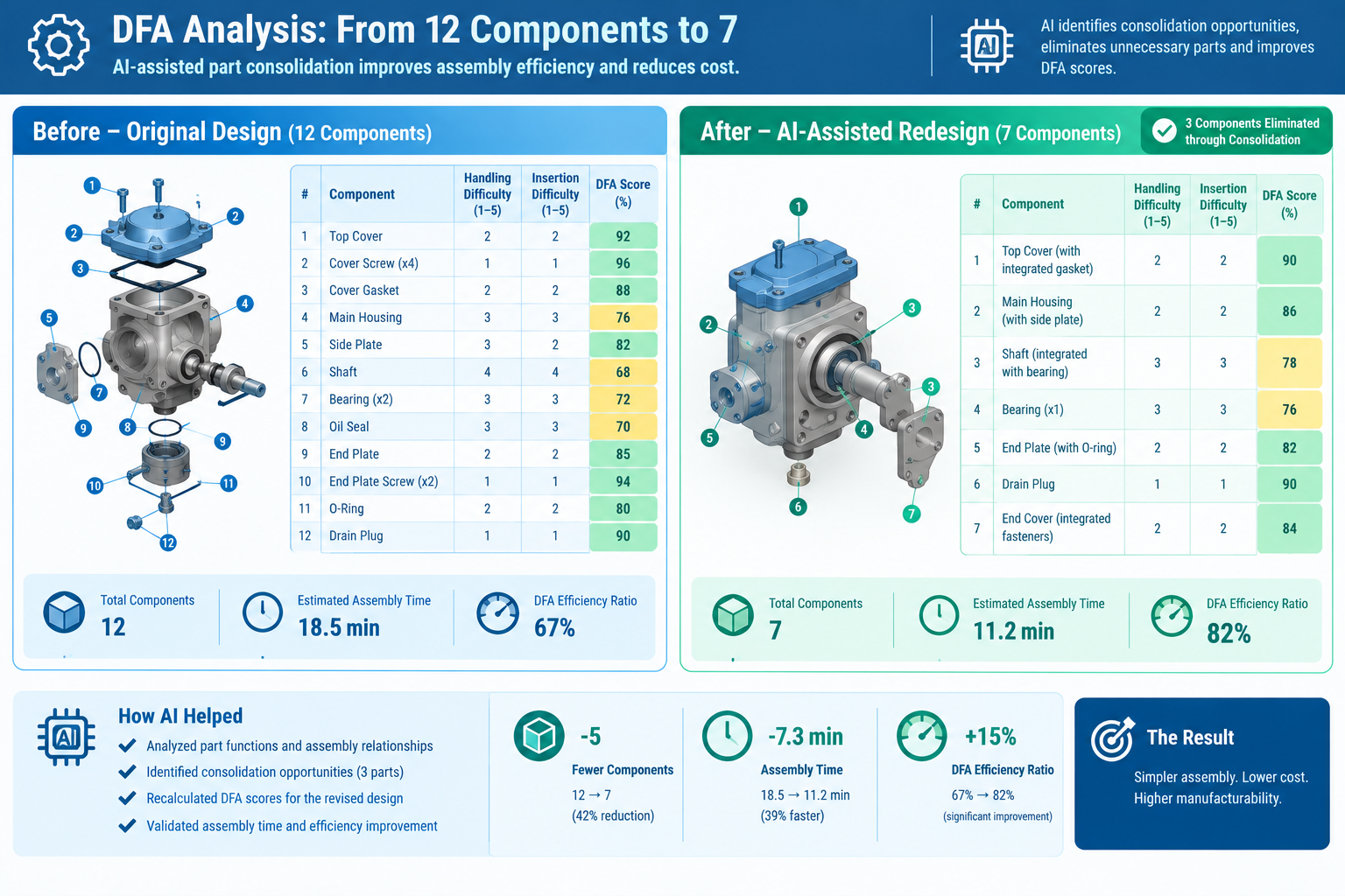
AI for the Boothroyd-Dewhurst DFA Methodology
The Boothroyd-Dewhurst DFA methodology evaluates each component in an assembly against two criteria: handling difficulty (how hard is it to pick up, orient, and handle the component before insertion?) and insertion difficulty (how hard is it to insert the component into the assembly, given access constraints and alignment requirements?). The methodology also applies the part elimination test, can this component be combined with an adjacent component without compromising function, material requirements, or maintenance access?
LLMs can apply the Boothroyd-Dewhurst framework systematically to a described assembly. When given a component list with descriptions of each component’s geometry, function, material, and assembly interface, the LLM evaluates each component for: symmetry (does it need orienting before insertion?), size and fragility (are there handling difficulties?), tangling potential (are springs, clips, or thin washers involved?), insertion accessibility (is the insertion path clear with adjacent components in place?), and the elimination test (what criterion prevents this component from being combined with its neighbour?).
AI for Assembly Error-Proofing (Poka-Yoke)
Poka-yoke (error-proofing) in assembly design means making it impossible or immediately obvious when a component is assembled incorrectly. AI can assist with poka-yoke design by identifying which components in an assembly are symmetric and could be installed in the wrong orientation, which components look similar to adjacent components and could be mixed up, and which assembly steps require force or tools that could damage the product if applied incorrectly.
LLMs reason about poka-yoke from assembly descriptions: ‘The motor mounting plate is square with 4 holes on a symmetric bolt circle. It can be installed in any of 4 rotational orientations, only one of which aligns the motor output shaft with the gearbox input. The 3 incorrect orientations will not prevent assembly (the bolt holes align in all 4 orientations) but will produce a non-functioning product. Recommend poka-yoke design features to prevent incorrect orientation.’ The LLM recommends options (asymmetric hole pattern, keyway feature, physical asymmetry to the mounting plate, colour coding) that the designer can implement.
AI DFM for Design to Cost
Design to Cost (DTC) extends DFM from ‘can it be manufactured?’ to ‘can it be manufactured economically?’ AI is making it possible to estimate manufacturing cost from CAD geometry during the design process, not just at formal quoting, enabling cost-driven design decisions at the point where they have the most impact.
AI Instant Manufacturing Cost Estimation
Online manufacturing services (Xometry, Protolabs, Fictiv, Hubs) now provide AI-powered instant manufacturing cost estimates at the point of design review. These tools analyse the uploaded CAD geometry and provide: an immediate cost estimate for the specified process, material, and quantity; DFM feedback identifying features that are increasing cost; and alternative process or material suggestions that could reduce cost while meeting requirements.
The most valuable cost insight from AI instant quoting is the marginal cost of specific design features. Knowing that the three 5-axis features on a bracket add $45 to the per-piece cost is an actionable design decision: is that feature worth $45? Could it be redesigned for 3-axis access at no functional cost? This cost-sensitivity analysis is only possible when instant AI cost estimation is available during the design process, not six weeks later when the toolmaker submits their quote.
AI for Process Selection Optimisation
AI can also assist with the upstream decision of which manufacturing process is most cost-effective for a given part design and production volume. The injection moulding vs CNC machining decision for a plastic housing depends on: production volume (tooling amortisation), part complexity, tolerance requirements, and lead time constraints. LLMs can reason through this decision from a part description and production volume requirement, applying the standard process selection logic and identifying the crossover volume at which each process becomes more economical.
| Design to Cost AI Application | Tool / Approach | Output | When Most Valuable |
| Instant unit cost estimate from CAD | Xometry AI, Protolabs AI, Fictiv AI | Per-piece cost by process and quantity, with DFM feedback on cost drivers | At design concept stage, before any tooling commitment, to understand cost order-of-magnitude and cost-driving features |
| Feature-level cost contribution analysis | Xometry AI cost breakdown, Protolabs configurator | Cost contribution by feature type (5-axis features, tight tolerances, special finishes) | When deciding whether to simplify specific features, AI shows the cost consequence of each simplification |
| Process selection comparison | LLM with production volume and complexity description | Break-even volume analysis for alternative processes; recommendation with justification | At early design stage when process has not been committed |
| Material cost comparison | LLM + materials database (Granta MI, MatMatch) | Cost per unit mass and per part for alternative materials meeting requirements | When evaluating material substitution for cost reduction, AI shows cost vs performance trade-off |
| Design to target cost iteration | LLM guided redesign; Xometry re-quoting after each iteration | Iterative cost reduction towards a target unit cost, with specific design changes at each iteration | When a design exceeds the target manufacturing cost and specific cost reduction changes are needed |
The Shift from Gate-Based to Continuous AI DFM
The most important change that AI enables in DFM practice is not better rule checking at the same gates, it is the elimination of gates as the primary model of DFM. Gate-based DFM treats manufacturability as a pass/fail criterion at a specific design review milestone. Continuous AI DFM treats manufacturability as a design parameter that is visible and tracked throughout the design process.
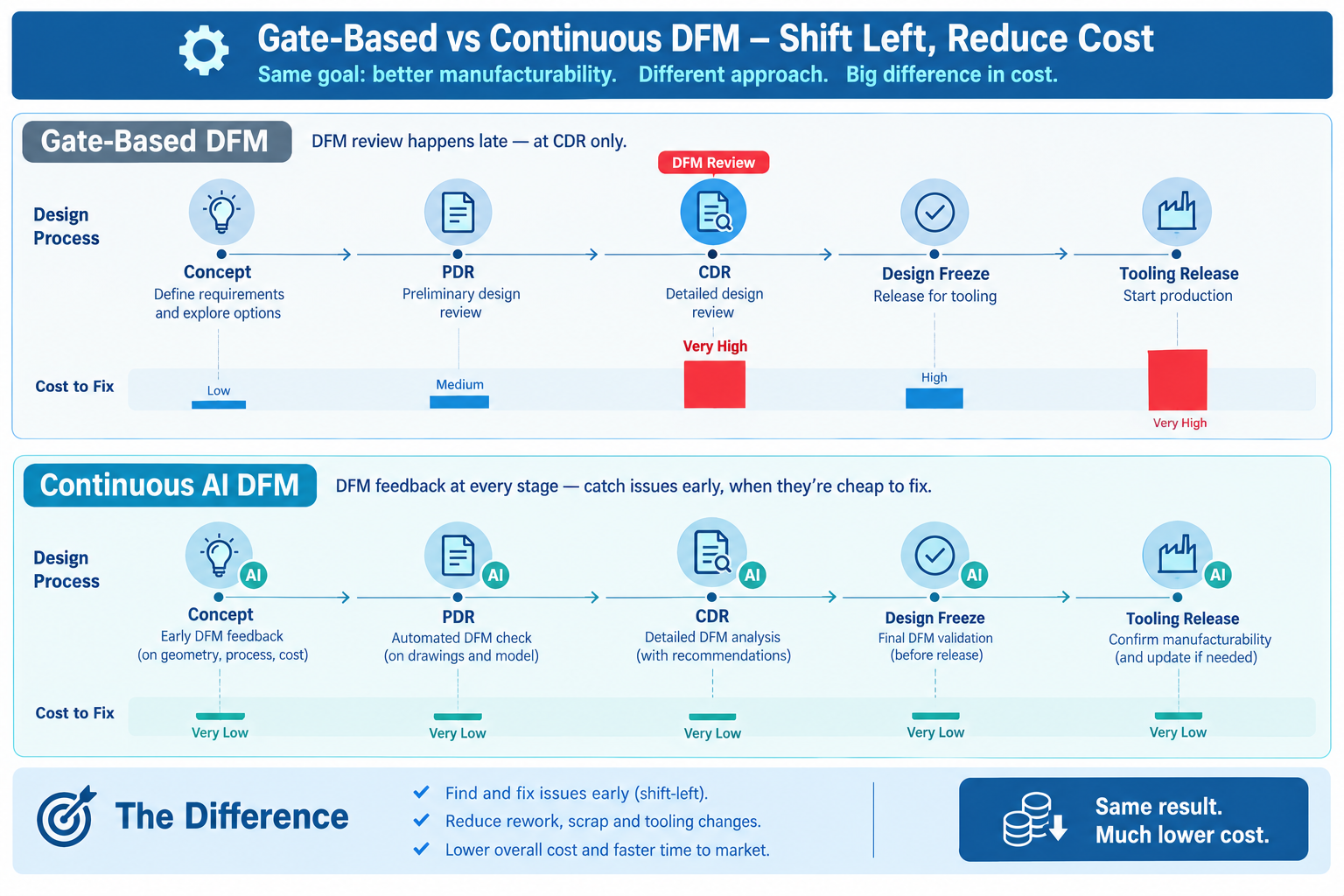
| Aspect | Gate-Based DFM (Traditional) | Continuous AI DFM |
| When DFM is performed | At formal design review gates (CDR, design freeze), after design is complete | Every time a significant design change is made, during design |
| Who performs DFM | DFM specialist or senior engineer at review gate | AI tool provides immediate feedback; engineer acts on it continuously |
| Cost of a found DFM violation | High, design is mature; changes require significant rework | Low, change is made to an evolving design before downstream commitments |
| Reviewer workload | High, reviewing a complete design at one gate | Distributed, AI handles systematic checking; reviewer focuses on judgement calls |
| Designer psychology | DFM feedback arrives after psychological commitment to the design; feels like criticism | DFM feedback arrives during design; feels like a design tool rather than a review |
| Coverage | Spot-check by a human reviewer; systematic violations on hidden features missed | Exhaustive, every feature checked every time AI DFM is run |
| Documentation | DFM review report produced at gate; informal process between gates | AI DFM report produced on every run; built-in design history of DFM compliance evolution |
Implementing continuous AI DFM requires two changes to the engineering workflow: integrating AI DFM tools into the CAD environment (DFMPro plugin, Xometry quoting as the standard quoting path) so DFM feedback is available without a separate analysis step; and changing the engineering team’s expectation, from ‘DFM is reviewed at CDR’ to ‘DFM is the designer’s responsibility throughout the design process, with AI tools providing continuous feedback.’
AI DFM Tools: Selection and Comparison
| Tool | Processes Covered | CAD Integration | Output Format | Pricing | Best For |
| DFMPro (Geometric Technologies) | Injection moulding, CNC machining, sheet metal, casting, additive manufacturing, most comprehensive coverage | SolidWorks, CATIA, NX, Creo as plugin; also Siemens Teamcenter and PTC Windchill | Detailed violation report with measured values, required values, severity, and CAD model highlights | $5,000-$20,000/year per seat depending on module | Engineering organisations where DFM quality is mission-critical; highest coverage, most detailed reports |
| Moldex3D (CoreTech System) | Injection moulding specialist, mould flow simulation + DFM | SolidWorks, CATIA, NX, Creo plugins; Moldex3D Studio standalone | DFM advisor report + full mould flow simulation results (fill, pack, cool, warp) | $15,000-$40,000/year | Injection moulding focused organisations; product design teams doing high-volume plastic parts |
| Autodesk Moldflow | Injection moulding specialist, mould flow simulation + gate optimisation AI | Fusion 360 integration; standalone; Inventor plugin | Fill analysis, gate optimisation, cooling analysis, warpage prediction | Subscription from $1,500/year (Insight basic) to $10,000+/year (Insight complete) | Fusion 360 and Inventor users; SME product design teams |
| Xometry Instant DFM | CNC machining, injection moulding, sheet metal, 3D printing, at point of quoting | File upload (.STEP, .STL) via web interface; no CAD plugin required | DFM feedback report + instant price estimate; actionable design suggestions | Free at point of quoting (cost recovered in manufacturing pricing) | All engineers regardless of CAD system; most accessible AI DFM tool available |
| Protolabs Instant DFM | CNC machining, injection moulding, 3D printing, sheet metal | File upload via web interface | DFM feedback report + instant quote; 3D model viewer with violation highlights | Free at point of quoting | Rapid prototyping programmes; teams that regularly use Protolabs for prototypes and first articles |
| Materialise Magics (with AI) | Additive manufacturing (FDM, SLS, DMLS, SLA), DfAM specialist | Import STL, STEP, OBJ; standalone software | AM build preparation + DfAM analysis: support volume, build time, minimum features, orientation analysis | $5,000-$15,000/year | AM-focused engineering teams producing metal and polymer AM parts |
| nTop (nTopology) | Additive manufacturing, topology optimisation and lattice design | Import/export STEP, STL, OBJ; API for automation | Topology-optimised geometry; lattice structure design; build-ready AM file | Subscription $5,000-$20,000/year | Advanced AM teams designing topology-optimised metal AM parts |
| LLMs (Claude, ChatGPT) | All processes, reasoning from description, not geometric measurement | None, works from text description and uploaded documents/images | DFM reasoning review, process trade-off analysis, cost reasoning, poka-yoke recommendations, design to cost guidance | Free to $20-$200/month subscription | All engineers for first-pass DFM reasoning, process selection, cost analysis, and DFM workflow without specialist software |
LLM Prompt Templates for DFM Review
The following templates are ready to use in Claude or ChatGPT for DFM analysis without specialist software.
Template 1: Comprehensive Injection Moulding DFM Review
Perform a comprehensive DFM review for the following injection-moulded plastic part. Material: [e.g. ABS, MFI 15 g/10min]. Nominal wall thickness: [VALUE]mm. Production volume: [VOLUME/year]. I will describe the geometry in detail: [DESCRIBE: overall dimensions, wall sections, ribs (height, thickness, location), bosses (height, diameter, proximity to walls), snap-fit clips (length, thickness, deflection direction), draft direction (which direction the mould opens), parting line location, any undercuts or side-action features, gate location if known, living hinges if present]. Review against these criteria and for each state Compliant / Marginal / Non-Compliant with the specific correction required: (1) Draft angles on all faces in the pull direction (minimum [1.0 / 1.5 / 2.0] degrees for [smooth/textured/deep-draw] surfaces in this material). (2) Wall thickness uniformity (maximum 25% variation from nominal). (3) Rib design: height <= 3x nominal wall; thickness = 0.6x nominal wall; base fillet >= 0.25x rib thickness. (4) Boss design: OD = 2x hole diameter; height <= 3x OD; base fillet. (5) Sink mark risk at thick sections. (6) Undercut detection. (7) Gate location feasibility. (8) Snap-fit deflection angle and cantilever geometry. Prioritise findings: Critical (prevents moulding) / Major (causes production defects) / Minor (increases cost or cycle time).
Template 2: CNC Machining DFM Review
Perform a DFM review for the following CNC machined component. Material: [e.g. 6061-T6 aluminium]. Available machining: [3-axis / 4-axis / 5-axis CNC milling centre]. Batch size: [QUANTITY/year]. Describe the key features: [DESCRIBE: pockets (depth, width, floor radius), bores (diameter, depth, tolerance), threads (size, depth, standard), holes (through/blind, diameter, pattern), critical surfaces (tolerance, location), features on non-primary faces, any thin walls]. Check each of the following and state Compliant / Non-Compliant with specific correction: (1) Are all features accessible from Z-axis on a 3-axis machine, or do any require 4th/5th axis or repositioning? Identify specifically which features require additional setups. (2) Internal corner radii, are all internal corners given a radius? What is the minimum radius achievable with a standard end mill at the pocket depth? (3) Pocket aspect ratios, identify any pocket with depth > 4x width; flag as high deflection risk. (4) Thread specifications, are all threads standard metric or Unified? Flag any non-standard pitches or forms. (5) Tolerance feasibility, identify any tolerance tighter than ±0.05mm on a feature > 100mm from datum; flag as requiring special process capability. (6) Thin wall sections, identify any wall < 1mm for aluminium or < 2mm for steel.
Template 3: Sheet Metal DFM Review
Perform a DFM review for the following sheet metal part. Material: [e.g. 2mm thick 304 stainless steel]. Available processes: [laser cutting, CNC punch press, press brake bending, spot welding]. Batch size: [QUANTITY]. Describe the flat pattern and key features: [DESCRIBE: sheet dimensions, bend locations (angle, direction, relation to holes and edges), hole locations (distance to edges, distance to bends, hole diameter), flange lengths, notches, tabs, any formed features]. Check each criterion and state Compliant / Non-Compliant with specific correction: (1) Minimum bend radius for this material and thickness (minimum = [1x / 1.5x / 2x] material thickness depending on material ductility). (2) Hole-to-bend distance (minimum = 2x thickness + bend radius). (3) Hole-to-edge distance (minimum = 1.5x thickness). (4) Minimum flange length (minimum = 4x thickness for standard V-die press brake). (5) Notch width (minimum = 1x thickness). (6) Are there any features that cannot be produced by laser cutting (blind holes, tapped holes, countersinks), these require secondary operations. (7) Estimate nesting efficiency from the described flat pattern dimensions, is there opportunity to improve material utilisation through geometry modification?
Template 4: DFA Assembly Review
Perform a Design for Assembly (DFA) review for the following assembly using the Boothroyd-Dewhurst methodology. Assembly: [NAME AND DESCRIPTION]. I will list each component: [LIST: component name, function, material, quantity, geometry description, how it interfaces with adjacent components]. For each component apply the DFA elimination test: (1) Does it move relative to other components during operation? (2) Must it be a different material from adjacent components? (3) Must it be separable for maintenance? If none apply, it is a consolidation candidate, recommend which component it should be combined with and what the combined geometry would look like. For components that cannot be eliminated: (4) Rate handling difficulty (symmetry, can it be installed in multiple orientations? Size and fragility. Tangling potential). (5) Rate insertion difficulty (access to insertion point with adjacent components in place; alignment features; fastener access). (6) Identify assembly error-proofing (poka-yoke) opportunities for any component that could be installed incorrectly. Calculate the theoretical minimum number of parts and the DFA efficiency ratio (theoretical minimum / actual component count).
Template 5: Design to Cost Analysis
Perform a Design to Cost analysis for the following component. Current design: [DESCRIBE GEOMETRY, MATERIAL, MANUFACTURING PROCESS]. Current estimated cost: [VALUE per unit at QUANTITY/year]. Target cost: [VALUE]. Analyse: (1) Which geometric features are most likely driving manufacturing cost above target? Rank the top 3 cost drivers by estimated impact. (2) For each cost driver, recommend a specific design change that would reduce cost with minimal functional impact, and estimate the cost saving. (3) Is the current manufacturing process optimal for this part at this production volume? Compare the cost economics of [alternative process: e.g. injection moulding vs machining; casting vs fabrication] at the stated production volume. (4) Are there material substitution opportunities that meet all performance requirements at lower material cost? (5) Calculate the cumulative cost saving from all recommended changes and assess whether the target cost is achievable. For the most impactful recommendation, describe the specific geometry change in enough detail to implement it in CAD.
Implementing AI DFM: A Practical Roadmap
Implementing AI DFM in an engineering team does not require a large capital investment or a multi-year transformation programme. The following roadmap delivers measurable DFM improvement within one product development cycle:
| Phase | Actions | Tools Required | Timeline | Expected Outcome |
| Phase 1: LLM DFM (immediate, zero cost) | Adopt LLM DFM prompt templates for all new design reviews; require LLM DFM review output as a CDR entry condition; train all design engineers on the DFM prompt templates in this article | Free LLM account (Claude.ai, ChatGPT) | Week 1-2 | First-pass DFM coverage on every part using LLM reasoning; DFM comments documented in review records; immediate improvement in DFM culture |
| Phase 2: Instant DFM at quoting (immediate, zero incremental cost) | Adopt Xometry or Protolabs as the standard prototyping quote path; make AI DFM report a mandatory output of the quoting step for all new tooling quotes | Xometry.com or Protolabs.com (free at quoting) | Week 2-4 | Quantified DFM feedback on every part at prototype stage; DFM violations identified before tooling commitment |
| Phase 3: Specialist DFM tool for primary process (3-6 months) | Evaluate and deploy DFMPro (or Moldex3D for injection moulding focused organisations) as a plugin in the primary CAD environment; integrate DFM run into design review checklist | DFMPro or Moldex3D licence ($5,000-$20,000/year) | Month 3-6 | Exhaustive parametric DFM checking on every part for primary manufacturing process; measured violation rates; documented ROI from prevented tooling modifications |
| Phase 4: Continuous DFM (6-12 months) | Configure DFM tool to run automatically at PDM check-in or on model save; make DFM report part of the model file bundle submitted for review; establish DFM KPI tracking (violation rate per part, violation rate at tooling release vs design stage) | DFMPro + PDM integration (SolidWorks PDM, Windchill, Teamcenter) | Month 6-12 | DFM shifts from gate to continuous; designers see DFM feedback during design not after; DFM violation rate at tooling release approaches zero for primary process violations |
| Phase 5: AI design to cost (12+ months) | Integrate AI instant costing (Xometry AI) into design workflow for cost-sensitive programmes; establish target cost by part as a design input; track cost evolution from concept to final design | Xometry AI pricing API or manual quoting workflow | Month 12+ | Design decisions informed by manufacturing cost data; programmes meet target cost at first article rather than after value engineering rounds |
Frequently Asked Questions (FAQ)
How does AI improve Design for Manufacturability?
AI improves DFM through automated tools that check CAD geometry for manufacturing violations and LLMs that assess process trade-offs, assembly implications, and cost-saving opportunities. This enables earlier error detection, faster design iterations, and lower correction costs.
What are the most important DFM rules for injection moulding that AI checks?
AI checks five key injection moulding DFM rules: draft angles, wall thickness uniformity, rib dimensions, undercuts, and gate location. These checks help prevent moulding defects, unmoldable features, and unnecessary tooling costs before manufacturing.
What is the best free AI DFM tool for engineers?
Free AI DFM options include Xometry Instant DFM and Protolabs Instant DFM for automated CAD feedback during quoting, plus Claude and ChatGPT free tiers for preliminary DFM reviews using geometry descriptions.
How does AI DFM work for additive manufacturing?
AI DfAM tools optimise additive manufacturing through overhang and support detection, build orientation optimisation, and topology/lattice design. Tools like nTop, Materialise Magics, and Fusion 360 Generative Design help reduce material use, build time, support requirements, and production costs.
Can I use ChatGPT or Claude for DFM review without specialist software?
ChatGPT and Claude can provide first-pass DFM reviews from detailed geometry descriptions. Specify the manufacturing process, material, dimensions, and key features. The LLM can flag potential violations, explain manufacturing risks, and suggest corrections, but specialist tools and engineering review are still needed for validation.
What is continuous AI DFM and how is it different from traditional DFM?
Continuous AI DFM runs manufacturing checks throughout the design process instead of only at formal review gates. By detecting issues early through CAD plugins and automated checks, it reduces correction costs, speeds up reviews, and helps designers make better manufacturing decisions.
Conclusion
AI does not change the principles of Design for Manufacturability, draft angles, wall thickness uniformity, accessible features, achievable tolerances, and assembly simplicity have been the fundamentals of DFM for fifty years. What AI changes is the systematic application of those principles: from occasional gate-based checking by experienced reviewers to continuous, exhaustive, quantified feedback available to every engineer throughout the design process.
The practical consequence is significant. DFM violations that previously reached tooling release, because they were on hidden faces, because the reviewer was not a DFM specialist for that process, because the review was rushed before a programme milestone, because the designer was the same person as the reviewer, are now caught in minutes, before any manufacturing commitment is made. The Rule of Ten makes the value of this shift computable: a DFM violation found during design costs one unit to fix. The same violation found after tooling release costs a hundred.
The implementation path in this article, from free LLM DFM templates and free instant quoting DFM tools to integrated specialist software and continuous DFM in the PDM workflow, is designed to deliver measurable improvement at each phase without requiring a large upfront commitment. Start with the LLM prompt templates today. Add Xometry or Protolabs instant DFM as the standard quoting path tomorrow. Evaluate DFMPro for your primary manufacturing process next quarter. Within one product development cycle, AI DFM will have become a standard part of your engineering practice, and your tooling modification rate will tell you how much it was worth.
Related Reading: AI for Product Design Engineers | Using AI to Detect Design Errors Before Manufacturing | How Engineers Use AI to Review CAD Models Faster | AI-Assisted Design Reviews for Mechanical Engineers | 50 Claude Prompts for Mechanical Engineers | 3D Modeling in CAD: The Complete 2025 Guide
Leave a Reply